
More actions
| IPhone XS | |
|---|---|
| Manufacturer | Apple |
| Code name | |
| Release date | 2018-09-21 |
| Device type | Phone |
This article is a stub. You can help Repair Wiki grow by expanding it
Guides
Explanatory Guides
| Type | Difficulty | |
|---|---|---|
| IPhone Charging Circuit Diagnostics Guide | ||
| Parts that are serialized on iPhones | Troubleshooting/Diagnostics | |
| Which iPhones Will Boot With Top Board Only | Troubleshooting/Diagnostics | 1. Easy |
Repair Guides
Create a Guide
Device pictures
-
-
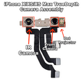
iPhone XS - TrueDepth Camera Assembly


PCB pictures

Reference measurements (also schematics if available)
-

iPhone XS - Known Good Mechanic Lightning Readings

More Information/External Sources
You can manually link to external sources for additional information that might not fit here but are useful such as BIOS image dumps, firmware, etc!
iPhone XS Schematics: https://www.sendspace.com/file/ynjkpn