More actions
No edit summary |
m (ASRepairs moved page Nvidia Turing GPU Diagnosing Guide to Nvidia Turing (RTX 2000) GPU Diagnosing Guide) |
(No difference)
| |
Latest revision as of 10:22, 16 March 2024
| Nvidia Turing (RTX 2000) GPU Diagnosing Guide | |
|---|---|
| Type | Troubleshooting/Diagnostics |
| Device(s) | RTX 2060, RTX 2070, RTX 2080, RTX 2080Ti |
| Difficulty | ◉◉◌◌ Medium |
This guide is relevant for most Turing-based cards ranging from 2060 to the 2080Ti. While some vendors might utilize distinct PCBs or components, the fundamental operational principles remain consistent unless explicitly stated otherwise. This guide uses a reference RTX 2080 as an example.
Have any questions? Need help with a specific GPU problem? Post to /r/GPURepair!
The Card Layout

Prior to any actions, it's advisable to visually examine the card for any signs of physical damage. This is particularly important for cards without backplates, as mishandling could potentially result in the loss of components from the underside.
Once you've confirmed the card's structural integrity, you can proceed to the next step using a multimeter to measure the resistances of the voltage rails
Step 1: Base Voltage Rails (12V, 3.3V)
What are the Base Voltage rails for GPUs? The base voltages are the ones that get supplied to the card through the motherboard and the external 8pin power connector(s).
12V rails
Graphics cards derive 12V from both the PCIe slot and additional 6-8 pin connectors.
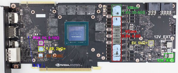
Start by measuring the resistance of the 12V rail from the PCIe slot. This involves checking the resistance across the first three pins of the slot or the highlighted green inductor in Figure 1.
Afterward, measure the resistance of each inductor linked to external power connectors. Some graphics cards have multiple external power connectors, each with its individual inductor needing measurement.
Remember, resistance values differ across graphics card models. The specific value isn't crucial; instead, resistance should generally range within several thousand ohms (Ω) or higher.
3.3V rail
The graphics card exclusively receives a 3.3V supply from the PCIe slot. This voltage is sourced from the fourth pin to the left of the PCIe key notch on the front side, as well as from the second and third pins on the rear side, again originating from the notch. These voltage points can be measured either directly or through the inductor indicated in Figure 1.
If you measure than 50Ω on one or multiple base rails then it indicates a short circuit within the card. Such a scenario may prevent the computer from powering on, as the power supply safeguards itself via Over Current Protection (OCP). To address this, refer to the dedicated page about Base Voltage Rail Short on Turing GPUs.
On the contrary, if no short circuit is detected, you can proceed with further troubleshooting.
Step 2: Minor Voltage rails. (5V, 5V USBC, 1.8V, VCore, VMem, and PEX)
Minor voltage rails are generated within the card itself from the base voltage rails, by either Linear Voltage Regulators or Step Down Buck Converters.
Measure the resistance of the output of those rails and compare them with Figure 1. VCore on 1000+ series cards has such a low resistance that it is useless to measure. A more helpful way is to measure its resistance against the 12v rails not GND.
It's worth noting that the 5V USBC rail, which powers the USB-C port, is a recent addition and is not available on all Turing cards. It is primarily used to energize the USB-C port and doesn't play a crucial role in the card's overall operation.
If you get lower resistance on one or more of those rails, head to their pages linked below.
Otherwise, continue with the guide.
Step 3: Powering on the card
Once you've confirmed the absence of any short circuits, proceed by inserting the card into the motherboard to initiate testing. Alternatively, you have the option to utilize a Lab Bench Power Supply along with a riser for card testing. This approach is safer for the motherboard and grants greater flexibility in maneuvering the card. Additionally, it provides insight into the card's current draw in the presence of a short circuit.
Switch your multimeter to DC Voltage mode and start measuring the base rails. If these voltage levels are detected, you can progress to evaluating the minor rails.
It's important to note that the minor rails activate in a series. If one of these rails fails to activate, the subsequent rails in the series will also remain inactive.
Power Sequence
The order in which they turn on in most Turing GPUs is as follows: 5V→ 1.8V→ VCore→ VMem/PEX.
For example, if 5v does not turn on, everything else in the chain won't turn on either. Hence no fan spin if you have a problem with 5V or 1.8V.
If you're missing one of them, check their respective page:
Step 4: No Video Out
Everything is present but still no video out? You either have faulty Memory, Bios, GPU chip itself, or in some cases a problem with straps.
Memory problems
If you've reached this point, the most likely culprit is the Memory. You can confirm this by powering on the card on the motherboard and plugging it in to the monitor, after a minute or so the monitor's backlight should turn on but without an image.
That behavior means the card initialized but detected a memory failure. Here: Nvidia Memory Testing Guide. is how to detect the faulty memory chips.
BIOS problems
If the memory is okay or the card is not even being detected in MATS then the problem is highly likely to be the bios. Check: BIOS Problems on Turing GPUs.
Straps
Configuration straps act like a switch to configure certain settings for the card. For example; memory type, memory capacity, enabling/disabling some functions etc.
Rarely, the strap resistors could become faulty and change in value or simply become an open line and prevent the card from working properly. Check their values outside of the circuit.


Crystal Oscillator
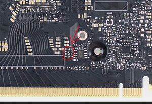
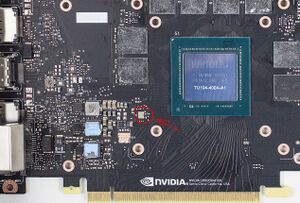
Often marked with Y followed by a number, crystal oscillators sometimes fail which will lead to the card not booting up.

In most if not all Turing GPUs, the frequency of the oscillator is 27MHz. An oscilloscope or a multimeter with Hz function that can go above 27MHZ is needed to test it.
Dead PCIE data lanes
If the card has been used for mining, there is a chance that the miner has inserted the riser backwards which can fry the first PCIE data lane inside the core. This video explains it more with a potential fix.
Faulty GPU Core.
If everything else is working as they should but still no video out then unfortunately you have a faulty GPU core. Best use for that card is as spare parts since getting hold of a GPU chip by itself is very hard and expensive and replacing it is a very advanced procedure that requires a BGA rework station and it's out of reach for many people.
Step 5: GPU outputs a picture
perhaps the card does output a picture but it is not working properly, here are the common problems and their potential fixes.
Artifacting
Artifacting is most often caused by memory problems, check Nvidia Memory Testing Guide
If you do not get memory errors even after 100+MB test in MATS then the core is very likely to be the issue.
Error 43
Just like artifacting, error 43 can be caused by faulty memory or core but also BIOS and straps.
Start by making sure the memory is fine as shown in the guide above, then check if the BIOS is not corrupted (flash original bios from either TPU library or manufacturer's site) and check the bios circuit as shown here: BIOS Problems with Turing GPUs
After that if the problem persists, check the strap resistors, they can either get knocked off or change in value which will trigger error 43.
If everything is fine but the error persists then the core itself is faulty.
