
More actions
| Raspberry Pi | |
|---|---|
| Manufacturer | Raspberry Pi Foundation |
| Code name | |
| Release date | 2012-02-29 |
| Device type | Other |
This article is a stub. You can help Repair Wiki grow by expanding it
Guides
Explanatory Guides
| Type | Difficulty | |
|---|---|---|
| Raspberry Pi LAN9514 | Circuit | 2. Medium |
| Raspberry Pi MXL7704 | Circuit | 2. Medium |
| Raspberry Pi PSU Test | Method | 1. Easy |
| Raspberry Pi RAM Test | Troubleshooting/Diagnostics | 1. Easy |
Repair Guides
Create a Guide
Device pictures
-
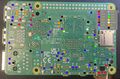
TP map of the Raspberry Pi 5
-
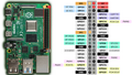
RaspberryPi GPIO Pinout
-
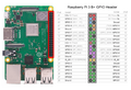
Raspberry Pi 3B GPIO Header
-
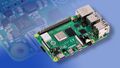
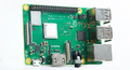
Raspberry Pi 4
-
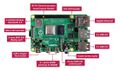
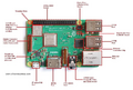
Parts of Raspberry Pi 4
-
Raspberry Pi 3B
-
Parts of Raspberry Pi 3B


PCB pictures
-
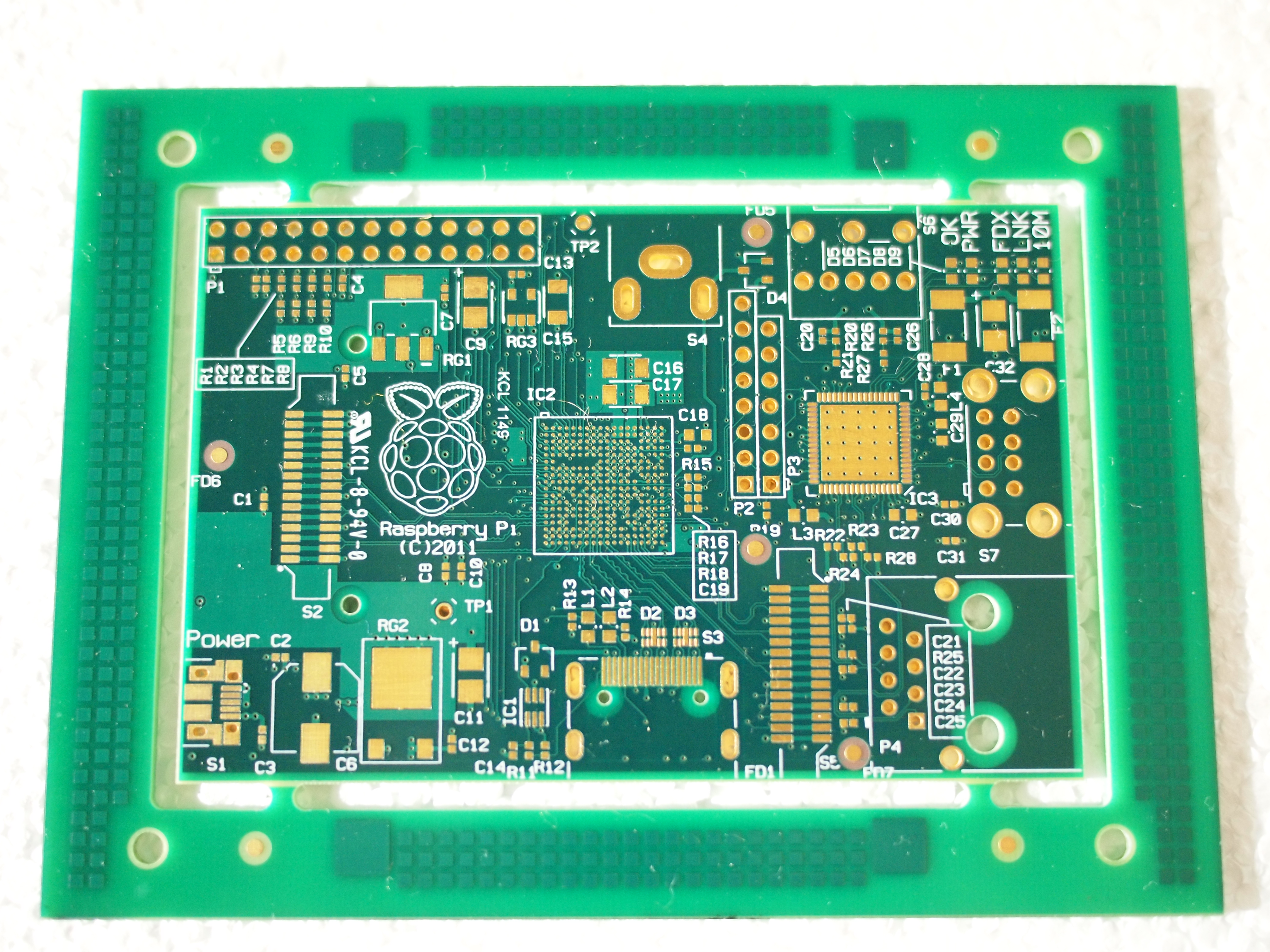
Model 1B PCB (Front)
-
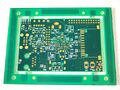
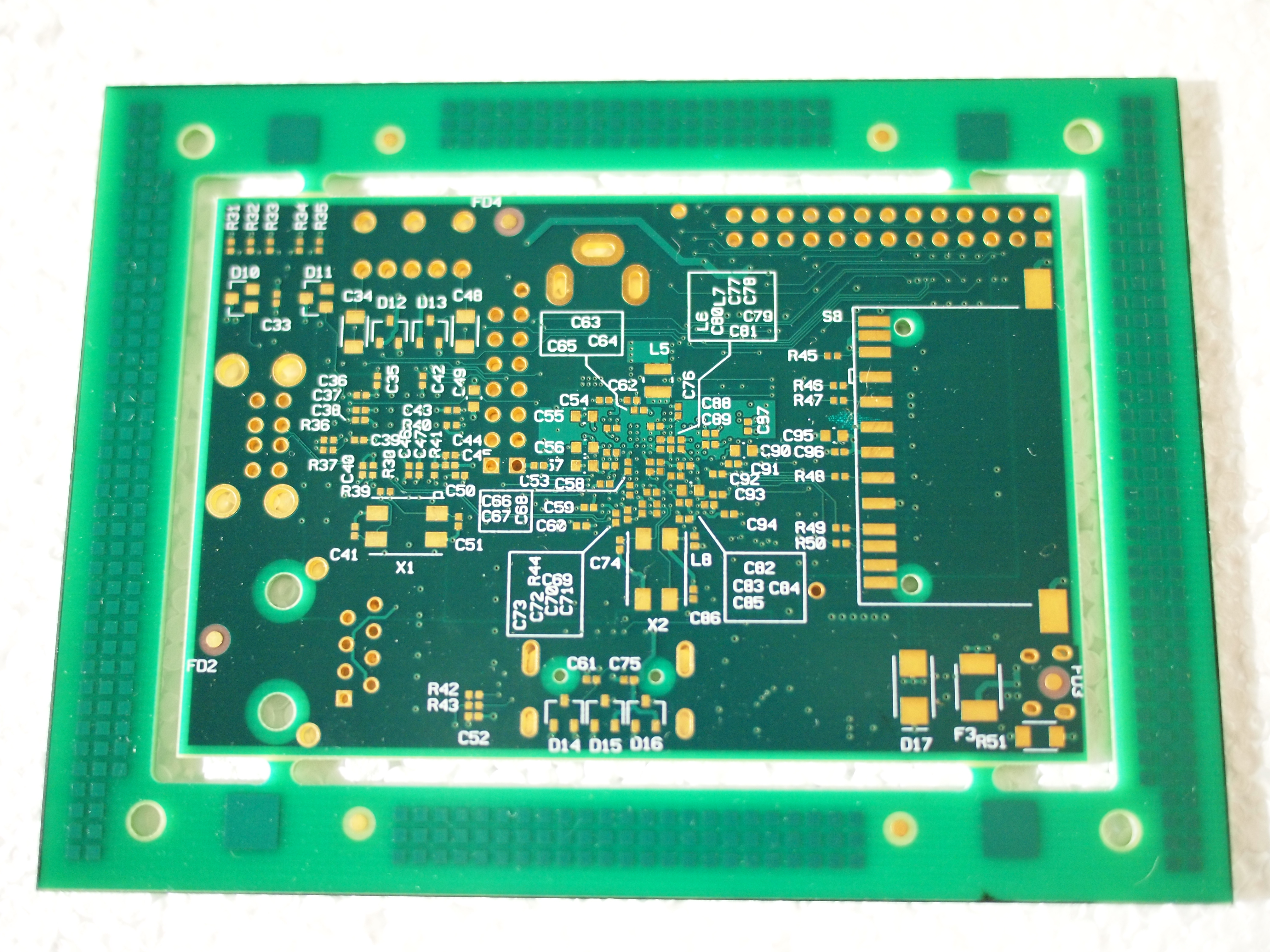
Model 1B PCB (Back)
-
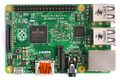
Raspberry Pi 2 Model B Top
-
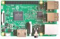
Raspberry Pi3 model B Rev1.2 Board overview (top)
-
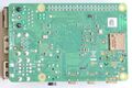
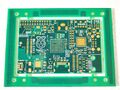
Pi4B underside


Reference measurements (also schematics if available)
Please consider contributing pictures to this section!
More Information/External Sources
About/Info
Raspberry Pi is a family of inexpensive single-board computers and microcontrollers.
Components are often reused from one Raspberry Pi model to the next, so solutions may work for multiple models.
The Raspberry Pi foundation provides various unorganized datasheets as well as thorough hardware documentation.
Raspberry Pi 1
Raspberry Pi 2
- Schematics: (Model 2B)
Raspberry Pi 3
- Schematics: (Model 3B), (Model 3B+), (Model 3A+), (Compute Module 3)
Raspberry Pi 4
- Schematics: (Model 4B)
Raspberry Pi 5
No official schematics have been released but a cute mechanical drawing is available
- Mechanical drawing: (Model 5)
Raspberry Pi Zero
- Schematics: (Pi Zero), (Pi Zero W)
- Raspberry Pi Zero PCB layers (click the dark gray button in the main post to view the layers)
Raspberry Pi Zero 2
- Schematics: (Pi Zero 2 W)