
More actions
| IPhone 7 | |
|---|---|
| Manufacturer | Apple |
| Code name | |
| Release date | September 16, 2016 |
| Device type | Phone |
This article is a stub. You can help Repair Wiki grow by expanding it
Guides
Explanatory Guides
| Type | Difficulty | |
|---|---|---|
| IPhone Charging Circuit Diagnostics Guide | ||
| Parts that are serialized on iPhones | Troubleshooting/Diagnostics |
Repair Guides
Create a Guide
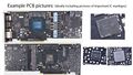
Device pictures

PCB pictures
-
-

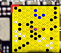
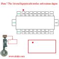
iPhone 7 Home Button Traces


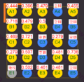
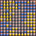
Reference measurements (also schematics if available)
-

iPhone 7 - Known Good Mechanic Lightning Readings
-
Homer IC Diode Values Intel
-
Audio IC Diode Values Intel
-
PMU diode value Qualcomm
-

BaseBand Diode Values Qualcomm
-

Touch And LCD FPC Diode Values - J4502
-

Rear Camera FPC Diode Values
-

Power Button FPC Diode Values - J4504
-

Front Camera FPC Diode Values - J4503
-

Home Button FPC Diode Values - J3801
-

Battery FPC Diode Values - J2201
-
Home Button Diode Values


More Information/External Sources
You can manually link to external sources for additional information that might not fit here but are useful such as BIOS image dumps, firmware, etc!
iPhone 7 Schematics: https://www.sendspace.com/file/iadz0j