More actions
m (typos) |
mNo edit summary |
||
| (5 intermediate revisions by the same user not shown) | |||
| Line 5: | Line 5: | ||
==Guides== | ==Guides== | ||
{{List Guides}} | {{List Guides}} | ||
==Device pictures== | ==Device pictures== | ||
<gallery showthumbnails="1"> | <gallery showthumbnails="1"> | ||
| Line 14: | Line 13: | ||
==PCB pictures== | ==PCB pictures== | ||
<gallery showthumbnails="1"> | <gallery showthumbnails="1"> | ||
File:Example pcb pictures.jpg| | File:Example pcb pictures.jpg|alt= | ||
</gallery><gallery caption="Controller Board pictures"> | |||
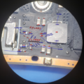
File:R Board REV B back - R1 test point.jpg|ButtonBoard Rev. B - R back side | |||
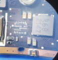
File:REV B left back mux.jpg|ButtonBoard Rev. B - L back side | |||
</gallery> | </gallery> | ||
==Reference measurements (also schematics if available)== | ==Reference measurements (also schematics if available)== | ||
<gallery caption="Schematics of the rev. B controller board (incomplete)"> | <gallery caption="Thermal Pad size<gallery> | ||
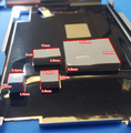
File:Thermal pad size on Steam Deck LCD Motherboard.png|Thermal pad size on Steam Deck LCD Motherboard. left (blue): charging ic pad, 5.4mm x 5.4mm x 4.5-5mm (squishy) | |||
</gallery>Schematics of the rev. B controller board (incomplete)"> | |||
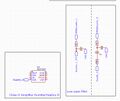
File:Power.jpg|Power delivery IC of the rev B controller board | File:Power.jpg|Power delivery IC of the rev B controller board | ||
File:Right trigger.jpg|Right trigger circuit of the rev B controller board | File:Right trigger.jpg|Right trigger circuit of the rev B controller board | ||
| Line 23: | Line 28: | ||
File:Rumble.jpg|Rumble circuit of the rev B controller board | File:Rumble.jpg|Rumble circuit of the rev B controller board | ||
File:Debug connector.jpg|Debug connector (TC-2050) of the rev B controller board | File:Debug connector.jpg|Debug connector (TC-2050) of the rev B controller board | ||
File:Buttons.jpg|R4/R5/"..." Button circuit of the rev B controller board | File:Buttons.jpg|R1(Shoulder)/R4/R5/"..." Button circuit of the rev B controller board | ||
File:FFC Connectors.jpg|FFC connectors (USB and connection to L board) of the rev B controller board | File:FFC Connectors.jpg|FFC connectors (USB and connection to L board) of the rev B controller board | ||
File:MODE-switch.jpg|Schematic for the mode-switch circuit to switch the MCU to programming mode - rev B board (Renesas MCU) | |||
</gallery><gallery showthumbnails="1"> | </gallery><gallery showthumbnails="1"> | ||
File:Steam Deck LCD F7A Ram Power Supply Diode and Idle Voltage.png | File:Steam Deck LCD F7A Ram Power Supply Diode and Idle Voltage.png | ||
| Line 62: | Line 68: | ||
ANX7580 Display IC: https://www.analogix.com/en/system/files/AA-004748-PB-1-ANX7580_0.pdf | ANX7580 Display IC: https://www.analogix.com/en/system/files/AA-004748-PB-1-ANX7580_0.pdf | ||
Headphone Jack: id: PJ-203B (brand: WNRE): https://www.ifixit.com/Answers/View/768877/When+will+a+replacement+audio+board+be+available | |||
Latest revision as of 13:51, 17 October 2024
This article is a stub. You can help Repair Wiki grow by expanding it
| Steam Deck | |
|---|---|
| Manufacturer | Valve |
| Code name | |
| Release date | February 25, 2022 |
| Device type | Game Console |
Guides
Explanatory Guides
| Type | Difficulty | |
|---|---|---|
| Steam Deck Mainboard Testing Points |
Repair Guides
| Affects part | Type | Difficulty | |
|---|---|---|---|
| Steam Deck - Flash MCU on controller board R rev. B | Controller board revision B; R7FA4E10B2CFM; R7FA4E10D2CFM | Software | 1. Easy |
| Steam Deck - Power Button: Middle pad ripped off | Steam Deck LCD Mainboard | Soldering Part replacement BGA | 3. Hard |
| Steam Deck - Replace shoulder switch R1/L1 | Controller Board | Soldering Part replacement | 2. Medium |
| Steam Deck - dump/modify controller board firmware | Controller board revision B; R7FA4E10B2CFM; R7FA4E10D2CFM | Software | 2. Medium |
| Steam Deck No power after NVME Replacement Repair | Motherboard | 3. Hard | |
| Steam Deck Not Charging Repair | Motherboard | Soldering | 3. Hard |
Create a Guide
Device pictures
-
Steam Deck
-
Steam Deck
PCB pictures
Please consider contributing pictures to this section!
- Controller Board pictures
-
ButtonBoard Rev. B - R back side
-
ButtonBoard Rev. B - L back side
Reference measurements (also schematics if available)
- Thermal Pad size
-
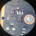
Thermal pad size on Steam Deck LCD Motherboard. left (blue): charging ic pad, 5.4mm x 5.4mm x 4.5-5mm (squishy)
-
-
Power delivery IC of the rev B controller board
-
Right trigger circuit of the rev B controller board
-
Some connections of the RA4E1 MCU of the rev B controller board
-
Rumble circuit of the rev B controller board
-
Debug connector (TC-2050) of the rev B controller board
-
R1(Shoulder)/R4/R5/"..." Button circuit of the rev B controller board
-
FFC connectors (USB and connection to L board) of the rev B controller board
-
Schematic for the mode-switch circuit to switch the MCU to programming mode - rev B board (Renesas MCU)
More Information/External Sources
iFixit provide a good chip diagram link: https://www.ifixit.com/Guide/Steam+Deck+Chip+ID/147811
Steam Deck OLED Chip ID (Chips on the controller boards are identical on OLED and LED versions - at least on controller boards with the Renesas MCU): https://www.ifixit.com/Guide/Steam+Deck+OLED+Chip+ID/167632
Steam Deck APU Deep Dive (Die Shots) https://www.youtube.com/watch?v=ERm1StY-4uY
Official Steam Deck CAD File: https://gitlab.steamos.cloud/SteamDeck/hardware
GamerNexus Steam Deck Hardware Analysis Video: https://www.youtube.com/watch?v=NeQH__XVa64
GamerNexus Steam Deck VRM Analysis: https://www.youtube.com/watch?v=dlsJB3narnk
Steam Deck Hardware Info: https://github.com/NKkrisz/Steam-Deck-Hardware
Recover Corrupt BIOS Through Crisis Mode: https://www.stanto.com/steam-deck/how-to-update-or-flash-your-steam-deck-bios-from-crisis-mode/
Unbrick Steam Deck BIOS Without A Backup: https://www.stanto.com/steam-deck/unbricking-your-steam-deck-without-a-bios-backup/
Unlocking The Steam Deck BIOS: https://www.stanto.com/steam-deck/how-to-unlock-the-lcd-and-oled-steam-deck-bios-for-increased-tdp-and-other-features/
MAX77958 USB-C PD Controller Datasheet: https://www.analog.com/media/en/technical-documentation/data-sheets/max77958.pdf
CS35L41 Audio Amp IC: https://www.cirrus.com/products/cs35l41/
P13USB102 USB 2.0 IC: https://www.diodes.com/assets/Datasheets/PI3USB102.pdf
MAX77961 USB-C Charging IC: https://www.analog.com/en/products/max77961.html
ANX7580 Display IC: https://www.analogix.com/en/system/files/AA-004748-PB-1-ANX7580_0.pdf
Headphone Jack: id: PJ-203B (brand: WNRE): https://www.ifixit.com/Answers/View/768877/When+will+a+replacement+audio+board+be+available


