More actions
| Gigabyte GTX 1080Ti Not detected (faulty AND gate) repair | |
|---|---|
| Device | GTX 1080Ti, GTX 1080 |
| Affects part(s) | Main Logic Board |
| Needs equipment | multimeter, soldering iron, soldering station |
| Difficulty | ◉◉◉◌ Hard |
| Type | Soldering |
Problem description
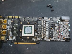
Fixing an issue with the Gigabyte GTX 1080Ti Turbo or Gaming OC (they use the same PCB) not being detected while the fans are spinning. This problem makes the GPU invisible to the rest of the system meaning not detected anywhere (MATS, Windows). And if you have a post card, you'll notice the motherboard zooms past B2 (state where the card would be detected) indicating the PC is not even trying to communicate with the card. For this repair, it is recommended to use a mining riser to make measuring easier.
This specific problem is related to the PCIE detection circuit, specifically, the PEX_RST AND gate.


Symptoms
- Not detected with fan spin.
- BIOS not being read, pins 2 and 5 silent when measured with an oscilloscope.
- All voltages present and core heating up normally.
- Vcore voltage stuck at 0.8V, not dropping to 0.7V to indicate an initialized core.
Solution
Diagnostic Steps
- Start by disassembling the card.
- Make sure there are no shorts on any voltage rail, follow this guide if you're unsure how.
- Power the card on with the riser with the data cable plugged in, this is important!
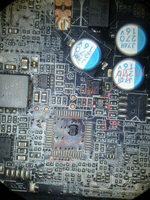
- Measure pins 1, 2, 4, and 5 on the AND gate (Figure 2) with your multimeter on voltage mode. Be careful when measuring as to not short anything!
- The "correct" measurement should yield 3.3, 3.3, 1.8, and 1.8V respectively.
- If you measure the correct values, you have a different issue! check the diagnosis guide or other guides on the wiki.
- If this is your issue, pin 4 should be reading close to 0V. Which indicates a faulty PEX_RST AND gate.
Repair Steps
- Take off the faulty AND gate.
- Replace with a suitable AND gate.
- You should now measure 1.8V on the output (pin 4) of the gate.
- Put the card back together and test!
On this card, the original was a "SN74LVC1G08" with "CEF" marking, I have replaced it with a "74LVC1G08" that has the marking "VE". Use Mouser or equivalent to buy the new part or take it from another donor.
