More actions
Here you'll find information about 1.8V circuit used on Turing cards.
| 1.8V Rail on Turing GPUs Explained | |
|---|---|
| Type | |
| Device(s) | |
| Difficulty | |
The Controller Circuit
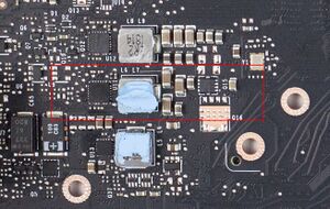
In Turing cards, you'll most likely find a GS9238 or similar buck converter that steps down 12V to 1.8V used to power low level logic inside the core and the bios chip(s)


Markings on the board and schematic may differ from one GPU vendor to another, however, the circuit is almost always the same.
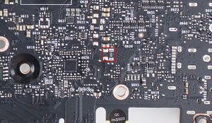
The controller steps down 12V on the input, either from the PCI-E slot or the external 8 pin connector(s) (based on which of 2 resistors is populated, see figure 2) to 1.8V on the output.
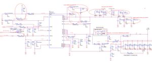
The FB pin is used to set the output of the controller through a resistor divider between it and Vout . In this case, for 1.8V out, a 10K/5K divider is used (see figure 3).
Enabling this controller is a signal coming from the and-gate (shown in figure 4) whose inputs are the PGOOD signal coming from the 5V Rail on Turing GPUs and the output of 2 voltage detectors one for 3.3 and the other for 12V_Bus.
VCC comes from the 5V rail through a resistor.
Usage
1.8V rail is used to:
- Power low level logic inside the core
- Pump voltage for VRAM
- Power the BIOS chip(s)
- As pull-up voltage for I2C bus data and clock lanes
- As pull-up voltage for SPI data and clock lanes
Common Problems
Here are common problems for the 1.8V rail and possible fixes.
No voltage out on the 1.8V rail
First thing to check is the EN signal which should be 2+ V followed by Vin which should be 12 V (Figure 3) if one of them is missing then check the schematic and follow the signal to find the culprit, it's usually a faulty resistor.
After making sure both of the above are there, check the VCC pin. If there is no 5 V on it then it's possible that the resistor between the 5V supply and the controller is blown open (controller could be short if the resistor is blown!)
Short on 1.8V rail
To find out what is shoring 1.8V, you need to inject 1.8V through the rail and with isopropyl alcohol or thermal camera find out what is heating up. The core or memory are a possibility(!)
No PowerGOOD signal
PGOOD signal is pulled high through an external resistor. If the output voltage is normal but there is no PGOOD then you need to check that resistor (Figure 3). If the resistor is fine but the signal is held low by the controller then the controller could be faulty.
Low voltage on 1.8V rail
This usually only happens with a faulty controller or faulty resistors in the FB circuit. First check if the resistor divider resistors are fine. If yes, then the controller is faulty.
