More actions
| VDDCI Rail on Polaris GPUs Explained | |
|---|---|
| Type | Circuit |
| Device(s) | RX 460, RX 470, RX 480, RX 560, RX 570, RX 580, RX 590 |
| Difficulty | ◉◉◌◌ Medium |
On this page you'll find information about VDDCI voltage rail on Polaris GPUs. How it works, what it is used for, and common issues with it.
The Controller Circuit
The creation of the VDDCI voltage rail depends on the VCore PWM controller used. In some instances, VDDCI is generated by the same VCore controller, such as the NCP81022 or UP9505P. Alternatively, a dedicated regulator like the GS7250 or a similar buck converter is used.
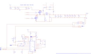
The PGOOD signal for VDDCI is generally not used for any specific purpose. VCC is supplied either from the 5V rail or from the 12V rail through a resistor. The Enable signal is sourced from the POK (Power OK) signal from the Display Rail controller. This POK signal switches an NPN transistor, which, in turn, switches another NPN transistor that is holding the enable signal low, as illustrated in Figure 3.


Please note that while markings on the schematic and board may vary among GPU models, the fundamental circuit design remains largely consistent.
Usage
VDDCI serves as the I/O bus voltage for the graphics card and is exclusively used within the core.
Common Problems
No VDDCI Voltage
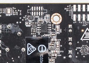
Initiate your troubleshooting process by measuring the EN and VCC pins of the controller. If either of these pins is low or shorted, the controller will not operate. If both pins are in high state, proceed to examine the FB circuit, as illustrated in Figure 2.
If everything appears to be in order, yet VDDCI remains missing, it could be indicative of a malfunctioning MOSFET. MOSFETs often exhibit short circuits when they fail, but at times, they can cease functioning without shorting. You can confirm this with an oscilloscope by measuring the gate of the MOSFET or the "UGATE" pin of the controller to verify whether the controller is generating the PWM signal. If no signal is present, the controller is likely dead.
After confirming the above checks are satisfactory but VDDCI is still absent, it may suggest a shorted VDDCI. In cases where VDDCI is created by the VCore controller, the VCore would also be missing. Follow the same diagnostic steps but for the VCore controller.
Short on VDDCI
A VDDCI measurement of less than 5 Ohms most likely indicates a dead GPU core. There is a chance that a capacitor could be the source of the issue. You can apply isopropyl alcohol to the capacitors and inject 0.9V into VDDCI to observe if any of the VDDCI capacitors heat up and evaporate the alcohol faster than the rest, which can help identify the shorted capacitor.
