More actions
(Added guide on firmware modding) |
mNo edit summary |
||
| (One intermediate revision by the same user not shown) | |||
| Line 5: | Line 5: | ||
|Needs equipment= | |Needs equipment= | ||
|Type=Software | |Type=Software | ||
|Difficulty= | |Difficulty=2. Medium | ||
}} | }} | ||
== WARNING! Only modify the firmware of the controller board, if you know what you are doing or are willig to sacrifice the controller board/Steam Deck. Modifications to the firmware can cause damage to the Software/Hardware of the controller board/Steam Deck. == | |||
== Necessary Software: == | == Necessary Software: == | ||
| Line 71: | Line 73: | ||
====== Dumping the firmware: ====== | ====== Dumping the firmware: ====== | ||
[[File:Fig. 1.jpg|alt=Motorola SREC file. relevant Firmware marked yellow|thumb|219x219px|Figure. 1: Motorola SREC file. relevant Firmware marked yellow]] | |||
Set the controller board to USB boot mode as described here: [[Steam Deck - Flash MCU on controller board R rev. B]] | Set the controller board to USB boot mode as described here: [[Steam Deck - Flash MCU on controller board R rev. B]] | ||
| Line 85: | Line 88: | ||
====== Motorola SREC format ====== | ====== Motorola SREC format ====== | ||
Read this: ''<nowiki>https://en.wikipedia.org/wiki/SREC_%28file_format%29</nowiki>'' | Read this: ''<nowiki>https://en.wikipedia.org/wiki/SREC_%28file_format%29</nowiki>'' | ||
[[File:Fig. 2 Notepad ++ Wrong SREC Checksum.jpg|alt=Figure 2: Notepad ++ Wrong SREC Checksum|thumb|225x225px|Figure 2: Notepad ++ Wrong SREC Checksum]] | |||
The chart on the top right of the wikipedia page should explain the format it sufficiently. | The chart on the top right of the wikipedia page should explain the format it sufficiently. | ||
===== Open the SREC File (in Notepad++) ===== | ===== Open the SREC File (in Notepad++) ===== | ||
Set the language to Motorola SREC | Set the language of the file to Motorola SREC. | ||
The | (see Figure 1): The blue characters (of the first 12 characters) are the Hex-address, the code is written to. | ||
The | The numbers in the middle (figure 1, yellow) are the firmware. | ||
The last two characters are the checksum. It has to be correct, in order to be written by the CLI tool | |||
Notepad++ is useful for this. It tells you, if the checksum is wrong. (Figure 2)[[File:Fig. 3.jpg|alt=Figure 3. Trimming the SREC file part 1|thumb|188x188px|Figure 3. Trimming the SREC file part 1]] | |||
====== Trim the firmware file ====== | ====== Trim the firmware file ====== | ||
You can use Notepad++ to cut out irrelevant parts. In the "search/replace" mode switch to "regular expressions". | You can use Notepad++ to cut out irrelevant parts. In the "search/replace" mode switch to "regular expressions". | ||
| Line 104: | Line 106: | ||
Delete the first line and the last line. It is just a comment. | Delete the first line and the last line. It is just a comment. | ||
In the replace function type <code>(.{2})$</code> to replace the last two characters | In the replace function type <code>(.{2})$</code> to replace the last two characters (Figure 3) | ||
Type <code>^.{12}(.*)</code> into „search for“ and <code>\1</code> into „replace with“ to cut the first 12 characters (Figure 4). | |||
The result should look like Figure 5.[[File:Fig. 4.jpg|alt=Figure 4. Trimming the SREC file part 2|thumb|190x190px|Figure 4. Trimming the SREC file part 2]] | |||
==== Edit the firmware ==== | ==== Edit the firmware ==== | ||
Paste the trimmed firmware into a hex editor like HxD (Figure | [[File:Fig. 5.jpg|alt=Figure 5. Trimmed SREC file|thumb|216x216px|Figure 5. Trimmed SREC file]][[File:Fig. 6.jpg|alt=Figure 6: Controller firmware in HxD|thumb|Figure 6: Controller firmware in HxD]] | ||
Paste the trimmed firmware into a hex editor like HxD (Figure 6) | |||
At the beginning, there is the bootloader area (see boot_ra_Release.srec). | At the beginning, there is the bootloader area (see boot_ra_Release.srec). | ||
| Line 120: | Line 122: | ||
There is also some other data. I have not figured out what is what. | There is also some other data. I have not figured out what is what. | ||
When you are done, either convert the file to the SREC format or flash the MCU with a bin file. | |||
<code>sudo ./rfp-cli -d RA -port /dev/serial/by-id/usb-Renesas_RA_USB_Boot-if00 00000000 data.bin</code> | |||
The command above should work. I have not tested this yet. | |||
You can also write parts of the firmware to the MCU. Read the documentation. | |||
== Happy modding. == | == Happy modding. == | ||
Latest revision as of 21:18, 21 October 2024
This article is a stub. You can help Repair Wiki grow by expanding it
| Steam Deck - dump/modify controller board firmware | |
|---|---|
| Device | Steam Deck |
| Affects part(s) | Controller board revision B; R7FA4E10B2CFM; R7FA4E10D2CFM |
| Needs equipment | |
| Difficulty | ◉◉◌◌ Medium |
| Type | Software |
WARNING! Only modify the firmware of the controller board, if you know what you are doing or are willig to sacrifice the controller board/Steam Deck. Modifications to the firmware can cause damage to the Software/Hardware of the controller board/Steam Deck.
Necessary Software:
All tools can be found in SteamOS under
/usr/share/jupiter_controller_fw_updater
They can also be found in the online repository:
https://gitlab.com/evlaV/jupiter-hw-support/-/tree/master/usr/share/jupiter_controller_fw_updater/
RFP-CLI
To dump the controller board firmware, the Renesas Flash Programmer CLI is used in this guide.
It can be used to read/write to the MCU via USB.
It can be found under
/usr/share/jupiter_controller_fw_updater/RA_bootloader_updater/linux_host_tools/rfp-linux-x64
The documentation for the rfp-cli program contains is a list with useful commands. Unfortunately, you have to download and install the Renesas flash programmer to read it.
https://www.renesas.com/en/software-tool/renesas-flash-programmer-programming-gui#downloads
The documentation "rfp-cli.md" can be found in the "docs" folder in the install directory.
Examples of Processing from Command Lines with the Use of rfp-cli
Examples are listed in the guide below (starting with page 14)
https://www.renesas.com/en/document/apn/renesas-flash-programmer-usage-command-line
Further tools
Firmware files:
- Bootloader file: boot_ra_Release.srec
- Controller Application: RA_APP_REL_6670771D.bin
Battery Control
Under /usr/share/jupiter_controller_fw_updater/RA_bootloader_updater/linux_host_tools
you will find the BatCtrl program. It can be used to power cycle the controller.
sudo ./linux_host_tools/BatCtrl SetCBPower 0
turns the USB Power off for the controller board
sudo ./linux_host_tools/BatCtrl SetCBPower 1
turns USB Power on
Commands to make the programs executable
chmod u+x "linux_host_tools/BatCtrl"
chmod u+x "linux_host_tools/rfp-linux-x64/rfp-cli"
Dumping the controller firmware
Using/modifying the flashing script.
I re-wrote chunks of the script under
/usr/share/jupiter_controller_fw_updater/RA_bootloader_updater/rfp_cli_linux.sh
to run my own commands.
Dumping the firmware:
Set the controller board to USB boot mode as described here: Steam Deck - Flash MCU on controller board R rev. B
Connecting the MD pin to ground is a easy way to do it.
To dump the firmware, you can simply use the following command:
sudo ./rfp-cli -d RA -port /dev/serial/by-id/usb-Renesas_RA_USB_Boot-if00 -read dump.srec
The firmware will be dumped in the Motorola SREC format.
Modifying the firmware
Motorola SREC format
Read this: https://en.wikipedia.org/wiki/SREC_%28file_format%29
The chart on the top right of the wikipedia page should explain the format it sufficiently.
Open the SREC File (in Notepad++)
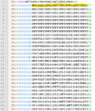
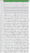
Set the language of the file to Motorola SREC.
(see Figure 1): The blue characters (of the first 12 characters) are the Hex-address, the code is written to.
The numbers in the middle (figure 1, yellow) are the firmware.
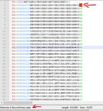
The last two characters are the checksum. It has to be correct, in order to be written by the CLI tool
Notepad++ is useful for this. It tells you, if the checksum is wrong. (Figure 2)
Trim the firmware file
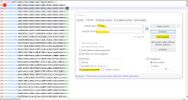
You can use Notepad++ to cut out irrelevant parts. In the "search/replace" mode switch to "regular expressions".
Delete the first line and the last line. It is just a comment.
In the replace function type (.{2})$ to replace the last two characters (Figure 3)
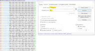
Type ^.{12}(.*) into „search for“ and \1 into „replace with“ to cut the first 12 characters (Figure 4).
The result should look like Figure 5.
Edit the firmware
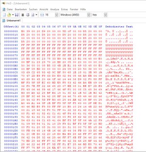
Paste the trimmed firmware into a hex editor like HxD (Figure 6)
At the beginning, there is the bootloader area (see boot_ra_Release.srec).
Between 0x00008000 and 0x00040000 sits the application data (see RA_APP_REL_6670771D.bin).
Between 0x08000000 and 0x08002000 there is provisioning and calibration data.
There is also some other data. I have not figured out what is what.
When you are done, either convert the file to the SREC format or flash the MCU with a bin file.
sudo ./rfp-cli -d RA -port /dev/serial/by-id/usb-Renesas_RA_USB_Boot-if00 00000000 data.bin
The command above should work. I have not tested this yet.
You can also write parts of the firmware to the MCU. Read the documentation.
