This page documents the Ecotality PE-30 EV charging station. This was a robust pedestal for public use, encapsulating the WE-30 hardware that Ecotality made for home use.
In the early 2010s, the US DoE funded a program ("The EV Project") to help solve the chicken-or-egg problem of public charging infrastructure vs EVs to use them. Ecotality Inc won the project and proceeded to seed the country, in several markets, with Level 2 charging stations branded as "Blink". For home charging these were WE-30 models; for public charging these were the heavier duty PE-30 model, which was just a WE-30 packaged in a heavy steel pedestal.
Ecotality and Blink then went through multiple rounds of bankruptcy and rebirth, and in the process the old PE-30 hardware was abandoned. Any site that wanted to continue operating their Blink hardware on the Blink network needed to upgrade to newer generation hardware. With Blink's high network / maintenance fees, many sites choose to abandon the stations. Without a Blink subscription, the old hardware ceased to work.
However, this old hardware actually reverts to being just a dumb EVSE if you disable the networking and UI hardware components. It is easy to "lobotomize" the hardware, disconnecting the network and UI layer, and turn them back into dumb stations that simply deliver power right away after you plug in.
Ecotality PE-30 model line
Model number
Part number
display height
PE-30Kice60
01-0131-0000
60 inches
PE-30Kice48
01-0135-0000
48 inches (ADA)
PE-30Kice40
01-0136-0000
40 inches (ADA)
Disassembly to access EVSE internals
Remove two security bolts (Torx security, 4 mm) at top of pedestal.
While lifting LED light assembly up, disconnect the wiring harness, and set the assembly aside.
Remove the two bolts at the top (hex, 10 mm).
At the charging cable management reel on the front of the unit, remove the white cosmetic cover; it pops out with help of a flathead screwdriver.
Remove the two (maybe 3-4) bolts (hex, 10 mm) that hold the reel onto the pedestal. You will need a nut driver for this, since the bolts are recessed in deep holes.
Tilt the large metal cover forward away from the pedestal assembly and lift it away. While you do this, you will need to feed the charging cable back through the grommet. You won't be able to disconnect the cover completely due to the attached cable, but you'll be able to set it aside.
Remove five bolts (hex, 10 mm) that hold the EVSE cover on; these should just be finger tight since they are fastening down plastic.
As you remove the EVSE cover, slowly peel the adhesive gasket off the touch screen.
It's not necessary to access the EVSE internals, but if you want to also remove the pedestal's back cover, use a regular (non-security) Torx T25 wrench. To lift it off the ground mount, you'll need a 1/2-inch box wrench.
Basic preventive maintenance
These action items are based on known problems with how this hardware was originally assembled, and should be performed if you are already opening up the unit.
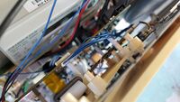
There is a current transformer on the power lines routed at the bottom of the internals. If allowed to drift left, this can pick up noise from (or generate noise to?) an adjacent component, disrupting operation. Therefore, gently push this CT to the right, so that it's next to the choke that's adjacent on the line.
Check the power terminal for stray wire strands. Some of the strands may not be captured inside the terminal blocks, and may lead to shorts. If found, remove and reinstall the wires.
See below for more significant rework procedures.
Disable network and touchscreen
These are the steps to disable the network / UI hardware, aka lobotomize it, so that the station Just Works as a dumb EVSE, simply providing power when you plug in.
PE-30 touchscreen assembly
Open up the pedestal per the steps above.
Look behind the touchscreen. Immediately behind it will be a PCB that drives the touchscreen (and the RFID sensor mounted below it). Behind that, about 300 mm further "back" and mounted on plastic standoffs, is another PCB which is a small Linux computer to drive the network connectivity.
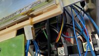
PE-30 touchscreen power disconnectedJust below the bottom of the touchscreen is a three-pin interface with three thicker blue wires going to it. This is providing power to one of the PCBs. Disconnect this. The photo here shows what it looks like after it's been disconnected.
PE-30 touchscreen data disconnectedOn the top edge of the computer PCB is a 10-pin interface with many thin blue wires going to it. This is providing data between the computer and the touchscreen. Disconnect this. The photo here shows what it looks like after it's been disconnected.
After performing this surgery and putting the unit back together, it is recommended that you remove any Blink branding -- most of it is just vinyl lettering that you can peel off, but some is embossed in the plastic and should be taped over. You should also tape over the touchscreen, perhaps with a sign saying "just plug in" and a mention of the host business that is generously giving away the free charging.
repair J1772 plug / cordset
The J1772 plug and cordset on these units had two problems.
First, not long after the deployments started in the early 2010s, the original Rema cordsets were found to have bad crimps in the J1772 plug. Blink's immediate action was to command the stations (over the air) to limit themselves to delivering 24 Amps instead of the 30 Amps they were designed for. In 2018, Blink deployed replacement cordsets (made by ITT Cannon, series J2CE) that restored the full 30A capability.
Second, the J1772 plugs on those ITT Cannon cordsets have a strange aging behavior, where the latching hook seems to "shrink". The hook surface shortens back towards the plug, eventually making it impossible to actually latch into a car's charge port. This typically starts as the plug requiring an extra "shove" to plug in, but eventually it become impossible to latch, and latching is a requirement for charging to start. The critical distance is from the plug's circular front surface to the latch hook surface; that distance should be 21-22 mm, but has been found to shrink to 19 mm. Fortunately, simply filing down that hook surface (back to 21-22 mm) should take care of it.
concrete base requirements
If you have lucked upon one of these units that's already been removed, and want to install it, here are the concrete base requirements:
1/2" thread anchors or L-bolts
six of above spaced in 2x3 grid that is 4.72" deep and 10" + 10" wide
1/2" studs should protrude 1.25" maximum from concrete pad
resources and more product photos
PE-30 installation manual; PDF-like document is embedded in page, and might be downloadable if you create an account there. Notable pages:
pp. 11-12: features and specifications
p. 13: model numbers and exact dimensions
p. 16: exploded view of entire pedestal assembly
p. A-1: dimensioned CAD drawing of concrete base needed