More actions
| A1278 MacBook Pro dim green light on charger repair | |
|---|---|
| Device | MacBook Pro A1278 |
| Affects part(s) | Charging Circuit |
| Needs equipment | Soldering/ Rework Equipment, Multimeter, Microscope |
| Difficulty | ◉◉◉◌ Hard |
| Type | Soldering |
Problem description
Device does not boot from battery or attempt to power on when plugged into charger. The charger light is dimly lit green

Symptoms
- Device doesn't boot via battery or charger
- Charger LED is very dimly lit green
Solution
First things first check both your charger and your DC-in board as both of these can cause this issue if faulty.
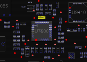
In most cases this issue is caused by a dead U7000 Power Management IC
This can also be caused by a dead component such as a fuse that stops power getting to U7000
Diagnostic Steps
Normally with this issue the best way to diagnose this is to start backwards so you can isolate your problem, with your multimeter in DC V mode check F7040 for 12.6v on PPBUS_G3H, If this is considerably low or 0v then the issue is isolated to either the circuit that powers U7000 or U7000 itself.
Once you have established that your PPBUS_G3H is low or nonexistent we can move on to checking your DCIN circuit. Check F6905 ensure it is continuous and not blown, we will assume here you are getting 16.5v on F6905 as you should have checked your DC-In board and charger by this point.
Now check to see if you have PP3V42_G3H on R7012. If PP3V42_G3H is present but PPBUS_G3H is not, U7000 is the issue.
There's a few more steps you can do, if you think the issue isn't U7000 follow the schematic on page 3 to try and find your issue, I cannot provide you with board views or schematics but they are very easy to find. Also if your PPBUS_G3H is 12.6v it's not U7000, I have once seen this be a short elsewhere on the board but it's quite rare in my experience and I cannot possibly cover or even know from the top of my head every little thing that could cause this but 99% of the time this issue is U7000.
Repair Steps
While this repair is pretty mundane and easy to most logic board tech's, there is a reason this has a 4 difficulty. If you do not have soldering experience and especially experience working with a hot air rework station on logic boards, attempting to replace a QFN as your first go probably won't be a fun time. This repair is more suited to people with experience as you can seriously destroy your logic board attempting this!
Equipment & Parts Needed
Soldering station - Ideally with a small knife tip for the smaller pads
Hot Air Rework Station - Since this is a QFN ideally use a decent station as a Yihua tier station takes forever to flow this IC
Microscope - You wouldn't be reading this guide if you had the skillset to replace this IC without one ;)
Solder and Flux - Obviously use quality leaded solder, I am not getting into a flux debate on this guide!
Solder wick - To clean the pads of the lead free solder
Tweezers - To grab the IC off the board and hold the new one on while soldering it.
A replacement ISL6259HRTZ
Screw Driver set to disassemble the machine and remove the logic board
A replacement ISL6259HRTZ is very easy to find across many online retailers such as eBay, AliExpress and other such places. In my experience buying these IC's they are going to be used, so if you have a donor logic board to extract one from it will save you a couple bucks!
Honestly if you have all this equipment you probably don't even need a guide haha but I will assume you have the logic board out the case and under your microscope at this point.
Step 1) Apply Flux and Tin the visible sides of the pads with leaded solder
Makes the IC a tad bit easier to remove, preheats it a tiny bit and also starts to mix leaded solder into the unleaded to make it easier to wick!
Step 2) Remove the IC
With a generous amount of flux applied, using your hot air rework station, heat the IC until the solder beneath it becomes molten. I like to run my Quick 861DW at around 350°C at 97 airspeed while doing this. You can check that the solder is molten by pushing the IC very lightly with your tweezers to check if it moves (As you would when you are replacing a CPU haha) once molten, carefully lift the IC from the board be careful to not knock the surrounding components.
Step 3) Wick the pad's & Apply fresh solder!
More flux! and apply some fresh leaded solder to the pad's and wick them clean! Once cleaned tin the small surrounding pads and put a very small blob of solder on the ground pad. You want just enough where the IC will solder down and have a good connection but not to much as it will squeeze out of the sides and short the smaller pads together
Step 4) Solder the new IC on!

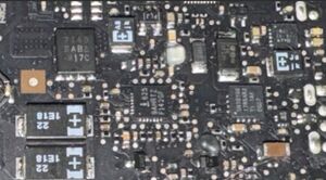
Incase you forget which way the Intersil logo points on U7000 once you have removed it and you have no other A1278's to compare with, I included a picture! :) (Don't bully me I actually had a complete brain fart and did this once years ago, fun times!) the i faces towards the RAM slots!
It's as simple as place the chip over the pads. align it so that you can see a very small amount of the little pads on all 4 corners, make sure it's aligned and flow the solder with hot air while lightly but firmly pressing the IC down with your tweezers until you feel it's aligned and the solder is completely molten. Then remove the hot air and hold the chip down for a few more seconds (moving your tweezers straight away is a novice mistake haha)
Clean up any blobs that may squeeze out the sides of the IC with your soldering iron and some more fresh flux! (If you have a micro pencil like a FM-2032 and a knife tip it's amazing for this).
Step 5) Clean up
Can't tell you how many boards I've seen with prior repairs that have flux left all over them! It's unprofessional and can cause issues later down the line! Use some 99% IPA and a cotton tip to clean the area up. I like to chuck these kind of boards in the ultra-sonic when done because they tend to be crusty from all the years of people eating over them! (Obviously a bit overkill)
Now your charger should fully light up! You should have 12.6v on PPBUS_G3H and your little old MacBook should be happy and fan spin! :)
