More actions
| 5V Rail on Pascal GPUs Explained | |
|---|---|
| Type | Circuit |
| Device(s) | GTX 1060, GTX 1070, GTX 1070Ti, GTX 1080, GTX 1080Ti |
| Difficulty | ◉◉◌◌ Medium |
This page explains how the 5V rail is created and what it is used for in Nvidia Pascal GPUs and the most common problems that could occur.
The Controller Circuit
Pascal graphics cards commonly employ either the RT7296F or MP1475 buck converter to transform the 12V_Bus rail into a 5V output.
The RT7296F is a synchronous step-down converter manufactured by RICHTEK. You can access its datasheet here
On the other hand, the MP1475 is produced by Monolithic Power Systems, and its datasheet can be found here
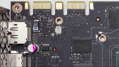
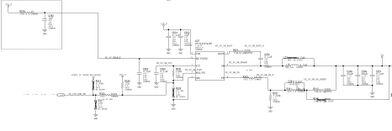
For reference, the location of the 5V rail on the board is illustrated in Figure 1, and the schematic for the 5V rail is provided in Figure 2.
It's worth noting that many GPU boards lack component markings, and when present, these markings may not always match the schematic. However, the underlying circuit remains consistent. For instance, U2 in Figure 1 corresponds to U27 on the schematic.
The 5V rail is a relatively straightforward rail and is typically the first to activate. The controller is enabled by the 3.3V rail through a 1kohm resistor, and capacitors serve to stabilize the voltage.
Most controllers require 5V on the VCC pin for operation. Notably, the RT7296F generates its own 5V supply for the VCC pin, drawing power from 12V_BUS along with some capacitors on the Vin pin.
The controller's primary function is to regulate the 12V input voltage down to 5V on the output. This regulation is achieved through a resistive divider connected to the FB pin (as shown in Figure 2).
Finally, if the power output remains within 90% of the expected voltage, the PG (Power Good) pin will transition to a high state. In most Pascal GPUs, the PG pin on the 5V controller is linked to the EN pin on the 1.8V controller via 0ohm resistor.
Usage
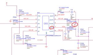
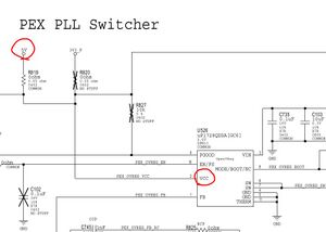
The 5V rail is most commonly used to power the VCC pins for other ICs on the board. Below are examples for 5V powering on the PEX and Vmem ICs.
Common Problems
Here are common problems for the 5V rail and how to fix them.
No voltage out on the 5V rail
First thing to check is the EN signal which should be 2+V followed by Vin which should be 12V (Figure 2) if one of them is missing then check the schematic and follow the signal to find the culprit, it's usually a faulty resistor.
After making sure both of the above are there, check the VCC pin. If there is no 5V on it then most likely the controller is faulty and needs changing. If there is 5V on VCC, check out the resistor divider and make sure their values are the same as in the schematic (Figure 2).
Short on 5V rail
5V supplies the VCC voltage for almost all the ICs on the board, thus you should look there first. If not, a capacitor might be shorted. To find the source of the short, Follow the steps in this guide: How to find short circuits.
Here is everything that is connected to 5V and might be causing a short:
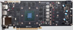
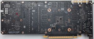
Everything marked with red is potential short location.
No PowerGOOD signal
PowerGOOD or "PG" or sometimes called "POK" is a signal which the controller outputs that indicates the state of the regulated voltage. If the regulated output voltage is within the limits, the PG signal will go high. Otherwise, it will stay low.
The PG signal from the controller serves as the enabling signal for the 1.8V controller. If the 5V buck converter fails to generate this signal, the remaining functions of the card will be compromised. The primary suspect in such cases is typically the controller itself in the case that the 5V output is present.
