More actions
| Samsung Galaxy A03s CPU Swap Step by Step Guide | |
|---|---|
| Type | Method |
| Device(s) | Galaxy A03s |
| Difficulty | ◉◉◉◉ Specialist |
Problem description
If you have a Samsung A03s that does not boot up, and all other efforts to fix the existing board has failed, then you can follow this guide on how to swap the paired chips onto another working board for the purposes of recovering the data that's trapped inside the chips.
🚨 Please Note 🚨
This process is super risky & requires tons of practice & skill to successfully do it.
If you damage the CPU or the UFS (Storage) chip, then it's game over. The data is gone forever.
So do not try this if you have no experience with CPU Swaps.
Absolutely DO NOT try this if you have no microsoldering experience.
I would recommend you practice on donor motherboards & once you can do it successfully 3 in a row, then you should have enough experience to do this on a live customer's board.
Recommended Tools
Hot Air Station: Atten ST-862D with 13mm Bent Nozzle
Soldering Iron: Aixun T420D with T210 Handle & JBC C210018 Knife Tip
Symptoms
- No Power
- Does not boot up
- No signs of life
- Board is cracked
- Board is water damaged beyond repair
Solution
Repair Steps
First, you need to locate the CPU and UFS.
- CPU holds the encryption keys
- UFS has the data, but it's encrypted
Both chips MUST be fully working & not damaged/cracked.
These chips talk to each other & during bootup, they exchange the keys so the phone can decrypt the data after the pin code is entered. Without the pin code, data cannot be decrypted & accessed.
Here's a picture of where these chips are:
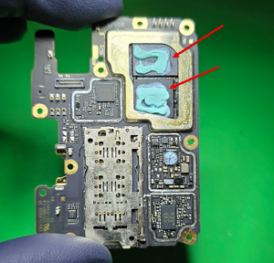
Typically, these are next to each other & very large chips. They also tend to have thermal paste or thermal pads. Sometimes they have shields completely covering them.
On this model, the CPU is labeled as MediaTek. So we can assume the other chip is the UFS.
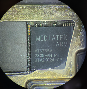
Now we must remove the shield around it to access the chips. I would recommend adding 138C Ultra Low Melt solder to the solder joints where the shield is attached to the board. Make sure to add plenty of flux & use a knife tip style iron
This will make removing the shield much easier
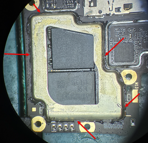
Using high temps, like 400C/60 air, heat around the perimeter
Use a hook tool or tweezers to grab onto the shield & pull it up, until it detaches, like this:
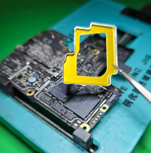
And now you have clear access to the 2 chips you need.
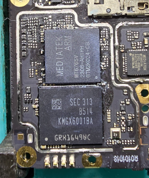
The CPU and UFS chips have hard & rubbery "glue" like substance that has these chips sealed to the board. This stuff is called "underfill". It must be cleared out with a sharp blade, like Scalpel #11 blade.
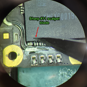
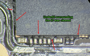
Go around all 4 sides of the CPU and UFS & get rid of it. This makes it so you can lift the chips easiest.
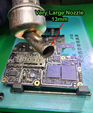
Switch to the largest nozzle your hot air station can support. For the Atten, we are using a bent 13mm nozzle
You're also going to need a very thin spatula blade. Use sandpaper to thin it out even further. Ideally, you'll want to taper the tip. This allow the blade to enter under the chip safely & cut through the underfill
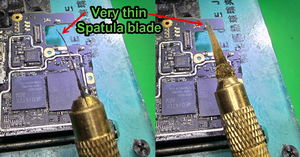
You'll want to use around 380C-400C to heat the chip in a circular motion. Make sure to start off far away, about 6in and heat in circles. This is to first warm up the board.
Over a 30 second period, get closer & closer until you're about 2-4mm away and always keep moving in circles.
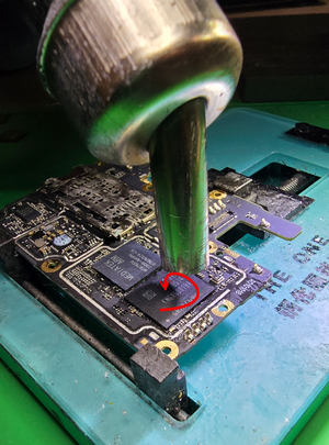
After about 30 seconds, the board should be very hot. This will make the underfill very soft.
Make sure to keep heating the IC in circles while still in close proximity.
Find an entry point, where there's no components and gently try to pry into the chip. But only go in horizontally. Maybe a little angled to try to get under, but stay as horizontal as possible
If you don't feel it budge, then don't force it in. Although some force is required, there's a fine point on what's too much. This is where lots of practice comes in to know what proper force is
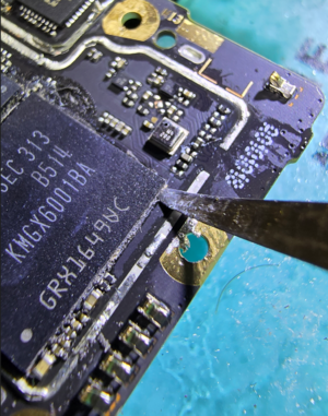
.As the spatula starts entering, do slicing motions, in and out. But do it gently.
You should be at about 60-90 seconds into this by this point.
If you're not having luck entering under the chip, try turning your temps & air flow up by 10 points and try again.
Don't heat the chip more than 2 or 3 minutes at a time. Reasses the situation & see if you need to adjust your temps more. If your tool is too thick. If maybe there's a better spot to enter.
Whatever you do, do not bend the chip up trying to remove it. You can damage it permamently & lose all chance to get data.
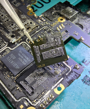
Once the chip is removed, inspect it for any damage. Look closely for any ripped pads or any scratches on the IC. This is where most go wrong & damage the chip. In many cases, if the chip gets damaged, then it's game over.
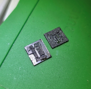
Then you'll have to repeat the same steps to ultimately remove the 2 important chips: CPU and UFS
