More actions
This article is a stub. You can help Repair Wiki grow by expanding it
| Raspberry Pi Faulty PAM2306 Repair | |
|---|---|
| Device | Raspberry Pi |
| Affects part(s) | |
| Needs equipment | |
| Difficulty | |
| Type | |
Problem description
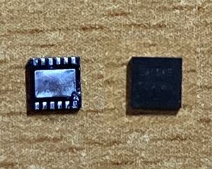
The PAM2306 is a dual step-down DC/DC converter that is used in the following Raspberry Pi models:
- Raspberry Pi 1 (A+ and B+)
- Raspberry Pi 2 (all)
- Raspberry Pi 3 (model B only)
- Raspberry Pi Zero (all)
Symptoms
Possible symptoms of a faulty PAM2306 include:
- System doesn't turn on or crashes immediately after turning on.
- System runs fine for 10 minutes, then turns off and won't turn on again for some time.
- Red PWR LED flickers or turns off completely (if present)
- 5V present at GPIO 2, but no 3.3V on GPIO 1
Solution
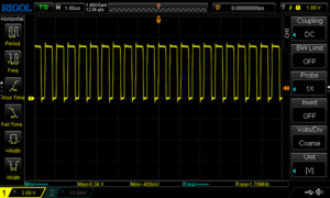
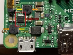
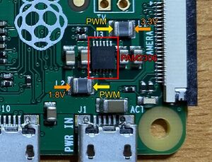
The PAM2306 drives both the 3.3V and the 1.8V power rails of the Raspberry Pi by producing two PWM (square wave) signals which are fed through coils connected to pins 8 and 2.
Usually, the generated square waves have a frequency of around 1.8MHz.
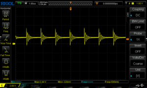
If a short circuit is detected, the frequency is reduced to around 600kHz, and shorter pulses are generated.
![The PAM2306 chip in the schematic of the Raspberry Pi 2[2]](/images/thumb/8/81/1200px-PAM2306_implementation_schematic.png/300px-1200px-PAM2306_implementation_schematic.png)
Diagnostic Steps
To find the exact fault, the following tests can be performed:
Supply voltage
To function properly, the chip needs a voltage of 5V on pins 1, 6 and 7. All those pins are directly connected to the Raspberry Pi's 5V rail, so testing for 5V on GPIO 2 will do.
If the voltage on GPIO 2 is close to 0V, the chip is most likely not the problem. Usually, the big diode near the micro-USB port needs to be replaced instead.
Coils
Remove all power from the Raspberry Pi and measure the resistance between the two sides of each coil (marked by orange and yellow arrows in the images). Measuring the coils directly can be tricky on some PCBs. Sometimes measuring between the PAM2306 and one of the brown capacitors is a better option.
If a coil is okay, the resistance should be a few Ohms at most.
Short circuits
Remove all power from the Raspberry Pi and measure the resistance between the voltage outputs (orange arrows) and the metal casing of the micro-USB port. There should be a resistance of many kOhms.
If there is a short circuit, the chip is most likely not the problem. Try locating the short circuit (see Detecting short circuits).
Analyzing the PWM signals
If an oscilloscope is available, the voltages at the PWM outputs of the chip can be analyzed directly (the two PWM outputs are marked with yellow arrows in the pictures).
- If there is no signal, but only a constant voltage on one of the PWM outputs, the chip is broken.
- If there is a 600kHz signal on one of the PWM outputs, and there is no short circuit, the chip is broken.
- If there is a 1.8MHz signal on both PWM outputs, the chip working fine.
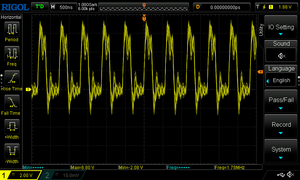
Depending on your probing technique, the measured signal may look quite a bit less clean than the square wave in the image above. This usually doesn't mean the PAM2306 is faulty, as long as the frequency is correct.
Repair Steps
Replacing the chip
If no other fault could be found in the above steps, the chip needs to be replaced.
Replacing the chip is only possible with hot air. Using a soldering iron is not possible because the chip has a soldered ground pad in its middle.
The cheapest and easiest way to get a replacement chip is to buy a Raspberry Pi Zero, or to take a chip from another broken Raspberry Pi.
Make sure to thoroughly check for shorts after replacing the chip (don't forget to check for shorts between the 1.8V and 5V rails as well as between the 3.3V and 5V rails!!).
References
- ↑ PAM2306 datasheet, Diodes Incorporated, May 2021
- ↑ Raspberry Pi 2 Model B schematic, Raspberry Pi Foundation, November 16, 2016
