More actions
(Created page with "{{Explanatory Guide}} Vcore, how it works, how it's created, common issues that happen on it. ==The controller circuit== Nvidia uses the [https://pdf1.alldatasheet.pl/datasheet-pdf/view/1222413/UPI/UP9511P.html UP9511p] by UPI Semi. The UP9511p is an 8-phase PWM controller on most Pascal high-end cards, in some cases (Like the hybrid version of EVGA cards) they use the [https://www.onsemi.com/pdf/datasheet/ncp81274-d.pdf NCP81274] instead. Markings on the schematic and...") |
No edit summary |
||
| Line 1: | Line 1: | ||
{{Explanatory Guide}} | {{Explanatory Guide | ||
|Device=GTX 1060, GTX 1070, GTX 1070Ti, GTX 1080, GTX 1080Ti | |||
|Type=Circuit | |||
|Difficulty=2. Medium | |||
}} | |||
Vcore, how it works, how it's created, common issues that happen on it. | Vcore, how it works, how it's created, common issues that happen on it. | ||
Revision as of 18:22, 6 November 2023
| VCore Rail on Pascal GPUs Explained | |
|---|---|
| Type | Circuit |
| Device(s) | GTX 1060, GTX 1070, GTX 1070Ti, GTX 1080, GTX 1080Ti |
| Difficulty | ◉◉◌◌ Medium |
Vcore, how it works, how it's created, common issues that happen on it.
The controller circuit
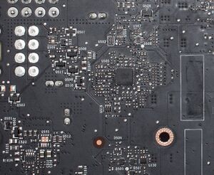
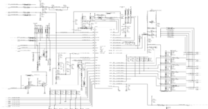
Nvidia uses the UP9511p by UPI Semi. The UP9511p is an 8-phase PWM controller on most Pascal high-end cards, in some cases (Like the hybrid version of EVGA cards) they use the NCP81274 instead.
Markings on the schematic and board could differ from GPU model to another but the circuit is almost always the same.


The controller gets powered up by the 5V rail through a 2.2Ohm resistor on pin 12.
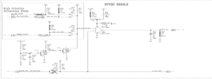
Enabling it is the PG signal from the 1.8V controller coupled with a protection circuit signal through an AND gate shown here:
The PG signal from this controller will enable the controller.
Nvidia uses the UP9511p, manufactured by UPI Semi, as the PWM controller in most of its high-end Pascal graphics cards. However, in certain cases, like the hybrid version of EVGA cards, they opt for the NCP81274 instead.
While the specific markings on the schematic and board may vary between GPU models, the core circuitry remains quite consistent.
To power up the controller, a 2.2-ohm resistor on pin 12 connects it to the 5V rail.
Enabling the controller relies on the PG signal from the 1.8V controller, combined with a protection circuit signal, processed through an AND gate as depicted in figure 3.
The PG signal emanating from this controller enables the VMem controller.
Usage
The PWM signals generated by the UP9511p controls the voltage going to power the GPU core. Switching 12V to 0.7-1V depending on the load on the GPU.
Depending on the model and manufacturer of the board and the components used, the PWM signals either go to the VRM directly, driver IC, or a doubler IC.
Common problems
No VCore voltage
In this case, check if the controller has 5V on its V, and 3V on EN. If one of them is missing trace their respective circuits and check for broken, knocked off, or defective components
If EN and Vcc are present and still no output, check the Vref pin, it should be 2V. If not, the controller itself is dead.
Very rarely the Imon resistor changes to a higher value which sets the output current limit to a lower value which could trip the OCP (over-current protection) of the controller.
Video example:
Nvidia GTX 1070 Board Repair (No EN for Vcore)
Short on VCore
By design, VCore has low resistance to GND (less than 1Ohm), so using a low-end multimeter won't be able to measure it accurately. Often times, the short happens on one of the VRMs. How to find them is explained here Base Voltage Rail Short on Pascal GPUs.
