More actions
mNo edit summary |
m (Added pictures.) |
||
| Line 10: | Line 10: | ||
<!-- | <!-- | ||
Provide a concise description of the issue here. Be as specific as possible to help readers quickly determine whether or not this is the exact problem they are facing. | Provide a concise description of the issue here. Be as specific as possible to help readers quickly determine whether or not this is the exact problem they are facing. | ||
--> | -->[[File:Shoulder switch.webp|thumb|Figure 1: Example of a new shoulder button switch with a ripped center pad (picture by u/veazix).]] | ||
A common problem with the controller board of the Steam Deck LCD are the shoulder switches, that can break off easily during disassembly. | A common problem with the controller board of the Steam Deck LCD are the shoulder switches, that can break off easily during disassembly. | ||
* | * | ||
| Line 25: | Line 24: | ||
Those switches have three pins and two legs (the latter for mounting through the pcb). | Those switches have three pins and two legs (the latter for mounting through the pcb). | ||
=== Repair Steps === | === Repair Steps === | ||
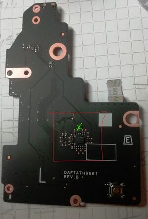
[[File:REV B left back mux.jpg|alt=Test point of the L1 shoulder switch on the rev B controller board - full view|thumb|Figure | [[File:REV B left back mux.jpg|alt=Test point of the L1 shoulder switch on the rev B controller board - full view|thumb|Figure 2: Test point of the L1 shoulder switch on the rev B controller board - full view. Red box: signal multiplexer. green arrow: testing point for the L1 switch.]] | ||
Swapping of the switches should be self-explanatory. | Swapping of the switches should be self-explanatory. | ||
In case the signal pads on the pcb get damaged: | In case the signal pads on the pcb get damaged (See Figure 1): | ||
On each controller board the leftmost and rightmost pin of the switch is connected to the ground plane of the board. | On each controller board the leftmost and rightmost pin of the switch is connected to the ground plane of the board. | ||
[[File:Back board l.jpg|alt=Test point of the L1 shoulder switch on the rev B controller board|thumb|Figure | [[File:Back board l.jpg|alt=Test point of the L1 shoulder switch on the rev B controller board|thumb|Figure 3: Test point of the L1 shoulder switch on the rev B controller board. red circle: testing point for the L1 switch.]] | ||
The middle pin is connected to the MCU/a signal multiplexer. On the left controller board you can strip the solder mask of the trace, running to the middle pin of the switch or connect the middle pin of the switch to the corresponding testing point for the L1 switch (see figure | The middle pin is connected to the MCU/a signal multiplexer. On the left controller board you can strip the solder mask of the trace, running to the middle pin of the switch or connect the middle pin of the switch to the corresponding testing point for the L1 switch (see figure 2 and 3). | ||
[[File:R Board REV B back - R1 test point.jpg|alt=Figure 3: Test point of the R1 shoulder switch on the rev. B controller board. green circle: testing point for the R1 switch. |thumb|Figure | [[File:R Board REV B back - R1 test point.jpg|alt=Figure 3: Test point of the R1 shoulder switch on the rev. B controller board. green circle: testing point for the R1 switch. |thumb|Figure 4: Test point of the R1 shoulder switch on the rev. B controller board. green circle: testing point for the R1 switch.]] | ||
On the right controller board, the middle pin is connected to the testing point visualised in figure | On the right controller board, the middle pin is connected to the testing point visualised in figure 4. | ||
[[File:Wire1.webp|thumb|Figure 5: Controller Board R, magnet wire connected to the center pin of the switch (picture by u/veazix).]] | |||
[[File:Wire2.webp|thumb|Figure 6: Controller Board R, magnet wire connected to the testing point on the back side of the board (picture by u/veazix).]] | |||
A possible fix for the right controller board might look like figure 5 and 6 if you run a magnet wire (enamelled wire) from the center pin of the switch to the testing point. | |||
Revision as of 17:40, 24 October 2024
This article is a stub. You can help Repair Wiki grow by expanding it
| Steam Deck - Replace shoulder switch R1/L1 | |
|---|---|
| Device | Steam Deck |
| Affects part(s) | Controller Board rev. B |
| Needs equipment | Soldering Iron, replacement switch |
| Difficulty | ◉◉◌◌ Medium |
| Type | |
Problem description
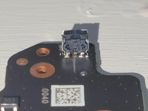
A common problem with the controller board of the Steam Deck LCD are the shoulder switches, that can break off easily during disassembly.
Solution
There are multiple compatible replacement switches. On Aliexpress they are sold as "Steam Deck switch" or "XBOX 360 pair switch".
Those switches have three pins and two legs (the latter for mounting through the pcb).
Repair Steps
Swapping of the switches should be self-explanatory.
In case the signal pads on the pcb get damaged (See Figure 1):
On each controller board the leftmost and rightmost pin of the switch is connected to the ground plane of the board.
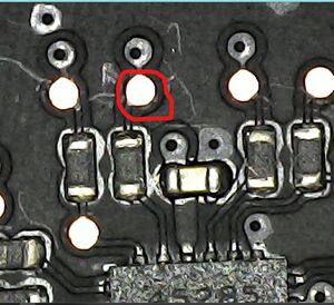
The middle pin is connected to the MCU/a signal multiplexer. On the left controller board you can strip the solder mask of the trace, running to the middle pin of the switch or connect the middle pin of the switch to the corresponding testing point for the L1 switch (see figure 2 and 3).

On the right controller board, the middle pin is connected to the testing point visualised in figure 4.
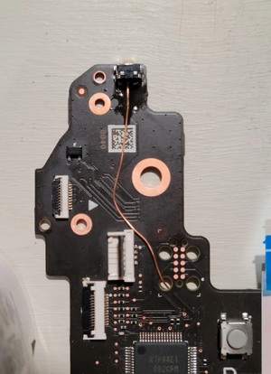
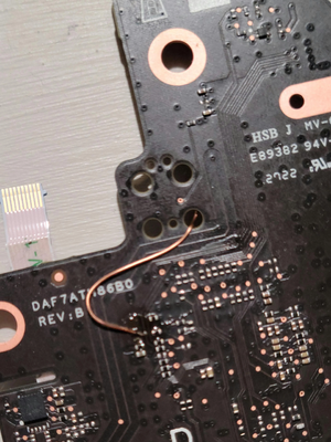
A possible fix for the right controller board might look like figure 5 and 6 if you run a magnet wire (enamelled wire) from the center pin of the switch to the testing point.
