More actions
(Initial transfer from old repair.wiki page) |
m (Found another project where someone reverse engineered a successor model.) |
||
| Line 17: | Line 17: | ||
The original schematic for several variants of the original IKA Combimag RET is detailed and contains individual part numbers for reordering a defect component. It also features the layout of both control and supply circuit boards that are in the device.<ref>https://www.sciencemadness.org/whisper/viewthread.php?tid=155043</ref> The schematic also features individual values for the passive components and typical voltage profiles in several areas of the circuit. | The original schematic for several variants of the original IKA Combimag RET is detailed and contains individual part numbers for reordering a defect component. It also features the layout of both control and supply circuit boards that are in the device.<ref>https://www.sciencemadness.org/whisper/viewthread.php?tid=155043</ref> The schematic also features individual values for the passive components and typical voltage profiles in several areas of the circuit. | ||
==== Ikamag RET-G ==== | |||
There is also [https://github.com/moeC137/Ikamag_RET-G_repair?tab=readme-ov-file this project on GitHub] where someone reverse engineered the Ikamag RET-G and drew all schematics in KiCad. The Ikamag RET-G seems the be a successor model of the Combimag RET. | |||
== Pictures == | == Pictures == | ||
Revision as of 10:53, 22 May 2024

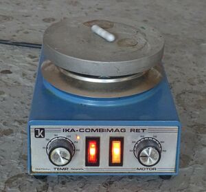
The IKA Combimag RET is an older model of a magnetic stirring plate with a heating function. It has a very robust design and all internal components (or equivalent substitutes) are still readily available.
Properties and issues
There is practically no documentation on the newer models[1] and their manuals[2] are descriptive at best. The most common solution is to "buy a new PCB and be done with it" because hardly anybody has the time to figure out the circuit first and then repair the issue.
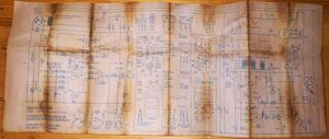
The unit incorporates two circuit boards (see schematic) that each mainly serve one purpose. One is responsible for the heating function and the other is used to control the motor of the magnetic stirring unit.
This makes problems easier to diagnose because (anecdotal) sometimes one function is slightly impaired before more significant issues arise. This gives a fair bit of forewarning to start diagnosing and ultimately repairing the unit.
One major issue is that the unit is air cooled and thus its components are susceptible to corrosive influences. You can observe this in a lot of units these days that come from a lab environment where corrosive chemicals were handled and used.
Diagnosing issues
Often issues can be traced back to faulty, corroded connections on one or several of the connectors that connect the components to the PCBs. In this case, the connections can be cleaned and often function resumes normally.
Schematic

The original schematic for several variants of the original IKA Combimag RET is detailed and contains individual part numbers for reordering a defect component. It also features the layout of both control and supply circuit boards that are in the device.[3] The schematic also features individual values for the passive components and typical voltage profiles in several areas of the circuit.
Ikamag RET-G
There is also this project on GitHub where someone reverse engineered the Ikamag RET-G and drew all schematics in KiCad. The Ikamag RET-G seems the be a successor model of the Combimag RET.
Pictures
-
Front of the Combimag RET in operation. A speed of 100 rpm is set for the PTFE stirrer.
-
Side view of the IKA Combimag RET the name plate can be seen in the right corner. The sticker is an indicator that this unit has passed the DGUV 3 check for mobile electric appliances in Germany.[4]
-
Back view of the IKA Combimag RET the DIN 45322 socket for the temperature probe can be seen in the lower right corner. The sticker is an indicator that this unit has passed the DGUV 3 check for mobile electric appliances in Germany.


![Side view of the IKA Combimag RET the name plate can be seen in the right corner. The sticker is an indicator that this unit has passed the DGUV 3 check for mobile electric appliances in Germany.[4]](/images/thumb/8/8c/Side_view_of_the_IKA_Combimag_RET.jpg/120px-Side_view_of_the_IKA_Combimag_RET.jpg)
