
More actions
(Added some information) |
|||
| Line 31: | Line 31: | ||
The DSP chip is called SAA7708H. The CD drive is connected to SPDIF1. The AUX stereo input, also known as the "Line In from NAV", also known as the green Mini ISO connector, goes to TDA8579 line receiver, and then goes to the TAPE_R/TAPE_l inputs of the DSP chip. The CD changer connections are passed into the CD_RI/CD_LI inputs of the DSP chip. | The DSP chip is called SAA7708H. The CD drive is connected to SPDIF1. The AUX stereo input, also known as the "Line In from NAV", also known as the green Mini ISO connector, goes to TDA8579 line receiver, and then goes to the TAPE_R/TAPE_l inputs of the DSP chip. The CD changer connections are passed into the CD_RI/CD_LI inputs of the DSP chip. | ||
There is a design error around the AUX input circuitry: The Electrolytic capacitor that connects to the "IN-" input of TDA8579 is placed with the wrong polarity. This results in the electrolytic capacitor getting reverse-charged, even without the AUX interface being in use. The reverse charging happens via high value resistors, so it is unlikely to end in the capacitor exploding, but if you choose to make use of the AUX input, then the polarity of this capacitor should be fixed. | [[File:Motherboard_of_PSARCD100-08_Capacitor_with_wrong_polarity_marked.jpg|thumb|Capacitor with wrong polarity (Figure 1)]] | ||
There is a design error around the AUX input circuitry: The Electrolytic capacitor that connects to the "IN-" input of TDA8579 is placed with the wrong polarity. This results in the electrolytic capacitor getting reverse-charged, even without the AUX interface being in use. The reverse charging happens via high value resistors, so it is unlikely to end in the capacitor exploding, but if you choose to make use of the AUX input, then the polarity of this capacitor should be fixed. Figure 1 shows the capacitor mounted with the incorrect polarity from the factory. It should be the opposite: The positive side should be towards the TDA chip next to it. (You can verify this both by measuring the voltage on the capacitor, and by looking at reference schematics of the TDA8579 chip. | |||
There is information available online on [https://www.instructables.com/Aux-in-jack-for-VDO-RD3-00-car-radio-Peugeot-Cit/ how to create and aux input cable] for this radio, however this hack has multiple problems with it: | |||
* The position where the signal is inserted, is between the DSP and the amplfier chip. For this reason the radio's volume control has no effect on the aux input, and the only way to select the aux input is to set the radio's volume to muted. | |||
* The external device and the DSP driving against eachother may damage eachother. | |||
* The advice above shorts the front and rear speaker outputs together, losing the ability to configure front-rear balance from the radio, and now two different outputs of the DSP are driving against eachother, which may damage them. | |||
Instead it would be better to use the AUX stereo connector, fix the incorrectly placed capacitor to be in the opposite orientation of Figure 1, and to enable the aux input using some car diagnostics software that supports enabling it. (the author of this paragraph has not tried the better modification yet, but is firmly against the advice found on the link above) | |||
There may also be commercial USB/Bluetooth accessories, that utilize the CD changer port, which should also be adequate. | |||
Revision as of 22:52, 11 February 2026
This article is a stub. You can help Repair Wiki grow by expanding it
| Siemens VDO RD3-01 Car Radio | |
|---|---|
| Manufacturer | Siemens VDO |
| Code name | PSARCD100 |
| Release date | |
| Device type | Car Radio"Car Radio" is not in the list (Laptop, Computer Component, Game Console, Phone, Tablet, Television/Monitor, Camera, Printer, 3D Printer, Drone, ...) of allowed values for the "Device type" property. |
Guides
Explanatory Guides
Repair Guides
Create a Guide
Device pictures
-
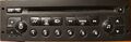
Front Panel
PCB pictures
-
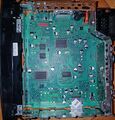
Motherboard of PSARCD100-08, Top
-
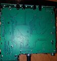
Motherboard of PSARCD100-08, Bottom


Reference measurements (also schematics if available)
Please consider contributing pictures to this section!
More Information/External Sources
Do not confuse this with the Clarion RD3-01 radio, the front panel looks similar, but the eject button is on the opposite side, and the motherboard is very different (for example the Microcontroller and DSP chips are all different)
The amplifier IC is always on, even when the ignition is off.
There is a 24C32 eeprom present on this board. It stores settings, such as saved radio stations, but it also stores the VIN of the car the radio came from. The VIN can be found in plaintext at the very end of the 4096-byte eeprom, from offset 0xFEF to offset 0xFFF, not even null-terminated. Due to its position it's likely that there are no checksums/hashes involved, so it may be very easy to modify the eeprom content to make it work in another car.
The DSP chip is called SAA7708H. The CD drive is connected to SPDIF1. The AUX stereo input, also known as the "Line In from NAV", also known as the green Mini ISO connector, goes to TDA8579 line receiver, and then goes to the TAPE_R/TAPE_l inputs of the DSP chip. The CD changer connections are passed into the CD_RI/CD_LI inputs of the DSP chip.

There is a design error around the AUX input circuitry: The Electrolytic capacitor that connects to the "IN-" input of TDA8579 is placed with the wrong polarity. This results in the electrolytic capacitor getting reverse-charged, even without the AUX interface being in use. The reverse charging happens via high value resistors, so it is unlikely to end in the capacitor exploding, but if you choose to make use of the AUX input, then the polarity of this capacitor should be fixed. Figure 1 shows the capacitor mounted with the incorrect polarity from the factory. It should be the opposite: The positive side should be towards the TDA chip next to it. (You can verify this both by measuring the voltage on the capacitor, and by looking at reference schematics of the TDA8579 chip.
There is information available online on how to create and aux input cable for this radio, however this hack has multiple problems with it:
- The position where the signal is inserted, is between the DSP and the amplfier chip. For this reason the radio's volume control has no effect on the aux input, and the only way to select the aux input is to set the radio's volume to muted.
- The external device and the DSP driving against eachother may damage eachother.
- The advice above shorts the front and rear speaker outputs together, losing the ability to configure front-rear balance from the radio, and now two different outputs of the DSP are driving against eachother, which may damage them.
Instead it would be better to use the AUX stereo connector, fix the incorrectly placed capacitor to be in the opposite orientation of Figure 1, and to enable the aux input using some car diagnostics software that supports enabling it. (the author of this paragraph has not tried the better modification yet, but is firmly against the advice found on the link above)
There may also be commercial USB/Bluetooth accessories, that utilize the CD changer port, which should also be adequate.