More actions
(Created page with "{{Explanatory Guide |Device=RX 5700, RX 5700XT |Type=Circuit |Difficulty=2. Medium }} Here you'll find information about 1.8V circuit used on Turing cards. ==The Controller Circuit== In Navi cards, you'll most likely find either a [http://www.gstekic.com/pdf/GS7260.pdf GS7260] (Full datasheet not available, used on non reference cards) or [https://www.monolithicpower.com/en/documentview/productdocument/index/version/2/document_type/Datasheet/lang/en/sku/MPQ8633AGLE-Z/do...") |
No edit summary |
||
| Line 4: | Line 4: | ||
|Difficulty=2. Medium | |Difficulty=2. Medium | ||
}} | }} | ||
Here you'll find information about 1.8V circuit used on | Here you'll find information about 1.8V circuit used on Navi cards. | ||
==The Controller Circuit== | ==The Controller Circuit== | ||
Latest revision as of 11:44, 24 March 2024
| 1.8V Rail on Navi GPUs Explained | |
|---|---|
| Type | Circuit |
| Device(s) | RX 5700, RX 5700XT |
| Difficulty | ◉◉◌◌ Medium |
Here you'll find information about 1.8V circuit used on Navi cards.
The Controller Circuit
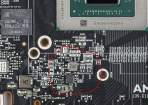
In Navi cards, you'll most likely find either a GS7260 (Full datasheet not available, used on non reference cards) or MPQ8633A buck converter (on reference cards) that steps down either 12V or 3.3V (Depending on the model) to 1.8V used to power low level logic inside the core and in some models the bios chip(s)


The controller steps down 12V/3.3V on the input, from the PCI-E slot.
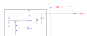
Enabling this controller is a detection circuit for 12V_BUS and 3.3V shown in figure 3.
VCC comes from 12V_BUS through a 1 Ohm resistor.
Usage
1.8V is mainly used on Navi to power low level logic inside the core.
Its PGOOD is used to enable the 0.75V rail
Common Problems
Here are common problems for the 1.8V rail and possible fixes.
No voltage out on the 1.8V rail
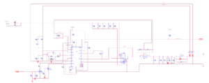
First thing to check is the EN signal which should be 3+ V followed by VCC /VIN (Figure 2). For the MPQ, VCC should be 3.3V and VIN should be 12V/3.3V. For the GS, VCC should be 12V. if one of them is missing then check the schematic and follow the signal to find the culprit, it's usually a faulty resistor.
After making sure both of the above are there, check the FB circuit, it is possible that one or more resistors are faulty.
Short on 1.8V rail
To find out what is shoring 1.8V, you need to inject 1.8V through the rail and with isopropyl alcohol or thermal camera find out what is heating up. If it is not a capacitor, then the core is a high possibility(!).
No PowerGOOD signal
PGOOD signal is pulled high through an external resistor to 3.3V. If the output voltage is normal but there is no PGOOD then you need to check that resistor (Figure 2). If the resistor is fine but the signal is held low by the controller then the controller could be faulty.
Low voltage on 1.8V rail
This usually only happens with a faulty controller or faulty resistors in the FB/COMP circuit. First check if the FB resistors are fine. If yes, then the controller is faulty.
