More actions
HaileyKitty (talk | contribs) m (typo fixed) |
No edit summary |
||
| (2 intermediate revisions by the same user not shown) | |||
| Line 1: | Line 1: | ||
{{Explanatory Guide|Device=CRT Displays}}CRT (cathode ray tube) are found on older televisions, monitors, and other equipment. | {{Explanatory Guide | ||
|Device=CRT Displays | |||
|Type=Troubleshooting/Diagnostics | |||
|Difficulty=3. Hard | |||
}} | |||
CRT (cathode ray tube) are found on older televisions, monitors, and other equipment. | |||
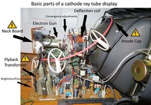
[[File:517px-CRT diagram.jpg|alt=Inside of CRT television with basic components labelled.|thumb|Inside of CRT television with basic components labelled.]] | [[File:517px-CRT diagram.jpg|alt=Inside of CRT television with basic components labelled.|thumb|Inside of CRT television with basic components labelled.]] | ||
| Line 76: | Line 81: | ||
# Once the tilt has been corrected to your satisfaction, re-tighten the screw then put the display back together. If your display has tilt correction in the OSD then any further small adjustments can be made in the OSD. | # Once the tilt has been corrected to your satisfaction, re-tighten the screw then put the display back together. If your display has tilt correction in the OSD then any further small adjustments can be made in the OSD. | ||
|} | |} | ||
[[Category:Television/Monitors]] | |||
Latest revision as of 11:45, 2 March 2024
| CRT Picture Adjustment Common Issues and Fixes | |
|---|---|
| Type | Troubleshooting/Diagnostics |
| Device(s) | CRT Displays |
| Difficulty | ◉◉◉◌ Hard |
CRT (cathode ray tube) are found on older televisions, monitors, and other equipment.

Safety Warning:
CRT displays contain extremely high voltage (up to 30,000v!) and the acts as a capacitor which can store a lethal charge for weeks after the display has been unplugged. The tube MUST be discharged properly before performing any kind of internal repairs.
Here is a good guide to refer to for discharging CRTs: https://www.youtube.com/watch?v=1CVXzlkOjGg
CRTs also contain mains voltage so general electrical safety precautions should be taken when working on them.
Service Manuals:
Due to the facts that most CRTs come from a time when repair was more common and companies didn't claim it was a security risk to have someone replace a failed capacitor, complete service manuals that included full schematics were often given out to independent repair shops, in the cases of older televisions they may have even been included with the television. Many of these manuals and schematics are now available online, simply look up the model of your TV/monitor and look for a service manual.
Descriptions and service manuals for Commodore monitors can be found here: Commodore monitors

Picture adjustment:
NOTE: Most picture adjustments should only be done after it has been confirmed that there are no faulty components on the board and those that are faulty have been replaced.
WARNING: For most of these adjustments to be effective, they must be performed while the CRT is turned on, make sure that you are isolated from ground and are using a nonconductive screwdriver to make adjustments. Stay clear of the neck board, anode cap, and exposed flyback circuitry whenever possible!
Over time, CRTs can go out of focus, misconverge, dim, or develop geometry issues; here is a very basic guide to troubleshooting and fixing such issues:
To start you are going to want a good testing image or program that can display images onto the CRT screen to aid you in adjusting focus or geometry. Here are some ways to do that:
- NEC test pattern generator is a program that will run on Windows and Linux (using Wine) and will generate test images onto your monitor for convergence, geometry, focus, and more.
- You can buy or make dedicated hardware that plugs into TVs or monitors and generates test patterns on the screen.
- You could burn a video calibration disc and play that onto the TV through a game console or DVD player. (Here is an example of one for NTSC TVs: https://archive.org/details/AvCalibrationNtscDvd)
- Some TVs or monitors may contain built-in test patterns that can be accessed through a service menu, check a service manual to see if they exist for your model and how to access them.
| Symptom/Issue | Adjustment/Fix |
|---|---|
| Images on screen appear blurry, particular at high resolutions. Is often caused by an out of focus CRT | Firstly, in the test pattern generator, go to the "Focus" or similarly named pattern, this will display a bunch of small dots on the screen, the goal of focusing the CRT is to make these dots as small and even as possible. Once the image is prepared it is time to begin making focus adjustments.
Secondly, a magnifying glass may be helpful, particularly for small or high-resolution screens to be able to see the dot size better. Some very old CRTs may contain a focus adjustment potentiometer externally, either on the front or the back of the unit, however this is uncommon and this explanation is for CRTs with internal pots on or near the flyback.
|
| Screen is dim, colours not showing up well. | While in some cases a dim screen and lack of vibrant colours can be a sign of the phosphors on the screen degrading which is not fixable. This can be temporarily fixed by adjusting the brightness but will cause the screen to degrade at a quicker rate. Afterwards, I would also recommend verifying colours are correctly displayed after. Some televisions and monitors may contain external adjustments for brightness and contrast, however, if your CRT does have those or if the external ones do not suffice then here is how to adjust the internal screen pot:
The "optimal brightness and vibrancy" will be different for different people so it is hard to give an exact measure of where it should be. it is important to note that having the screen too bright can increase the speed in which the phosphor degrades to the point where no amount of adjustment can bring the brightness or colour back. If this adjustment was done when the phosphor was already starting to go then it may work as a temporary fix but it will not last forever. |
| Misconvergence, one colour sticks out from the rest on edges between light and dark, or in extreme cases the colours have completely separated from each other. | Information coming soon |
| Tilted Image, the whole image appears to be slightly (or in rare cases drastically) tilted. | Issues like this often stem from physical abuse of the display causing the deflection coil assembly to loosen and twist. The deflection coil is responsible for bending and moving the straight beam of the electron gun(s) in a way that creates the picture on the screen, it does this magnetically so if it is physically tilted then the whole image on the screen will appear to be tilted.
Most modern CRT monitors and TVs will have some form of tilt correction in the OSD. On monitors it is typically in the user settings while on TVs you may have to access the service menu (Refer to mthe anual on your TV for how to access.) In the case of there only being a small tilt in the display then using these adjustments is a good way to correct it. These adjustments are also a good way to fine-tune after making a physical adjustment. Not all displays have the tilt correction setting or the tilt correction may not be working/not be enough to correct the tilt on your display. For this, you can make a physical adjustment to the deflection coil assembly.
|
