[[File:EtbBPxMExGLTlA4g d830df52-76b5-4b70-b2b0-e78e3ba42d62.png|thumb|471x471px|Figure 1. Front side of Nintendo Switch motherboard with the LCD connector circled in red and the backlight connector circled in blue]]<!--
[[File:EtbBPxMExGLTlA4g d830df52-76b5-4b70-b2b0-e78e3ba42d62.png|thumb|397x397px|Figure 1. Front side of Nintendo Switch motherboard with the LCD connector circled in red and the backlight connector circled in blue]]<!--
Detail all measurable or observable symptoms in this section.
Detail all measurable or observable symptoms in this section.
-->
-->
Line 25:
Line 25:
The problem is going to be related to either the LCD itself or the LCD circuit.
The problem is going to be related to either the LCD itself or the LCD circuit.
* [[File:55655B83-25E2-471F-AC87-15C37CF83F7C 1 201 a.jpg|thumb|Figure 2. Back side of Nintendo switch motherboard showing locations of backlight circuit points of interest with the backlight IC circled in red and test points circled in blue|316x316px]]First you will want to test with a known good LCD. You can dry fit a working LCD without removing the original by either just the bottom backlight cable or dry fitting both the LCD ribbon and backlight ribbon. See Figure 1 for reference on the locations of these connectors
* [[File:55655B83-25E2-471F-AC87-15C37CF83F7C 1 201 a.jpg|thumb|Figure 2. Back side of Nintendo switch motherboard showing locations of backlight circuit points of interest with the backlight IC circled in red and test points circled in blue|316x316px|left]]First you will want to test with a known good LCD. You can dry fit a working LCD without removing the original by either just the bottom backlight cable or dry fitting both the LCD ribbon and backlight ribbon. See Figure 1 for reference on the locations of these connectors
** If just the backlight ribbon is plugged in and the backlight circuit is working you should notice a slighter brighter screen when Switch is turned on, if the backlight circuit is bad then there will be no difference in the brightness of the screen
** If just the backlight ribbon is plugged in and the backlight circuit is working you should notice a slighter brighter screen when Switch is turned on, if the backlight circuit is bad then there will be no difference in the brightness of the screen
** If you want to test with the backlight and LCD ribbon plugged in you will have to bend the LCD cable a bit to test without fully installing it. If you do this be very careful to not bend the LCD cable too much as it is pretty fragile and can easily rip and ruin your known good LCD
** If you want to test with the backlight and LCD ribbon plugged in you will have to bend the LCD cable a bit to test without fully installing it. If you do this be very careful to not bend the LCD cable too much as it is pretty fragile and can easily rip and ruin your known good LCD
* If you test with a known good LCD and still aren't getting a working backlight then your problem is going to be related to the backlight circuit.
* If you test with a known good LCD and still aren't getting a working backlight then your problem is going to be related to the backlight circuit.
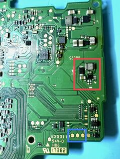
* [[File:DDDFB133-3764-46E2-B95D-2A806FA4B9A8 1 201 a.jpg|thumb|319x319px|Figure 3. Backlight test points on the opposite side of where the backlight connector is on Nintendo Switch]]First check the backlight connector for damage or loose pins
* First check the backlight connector for damage or loose pins
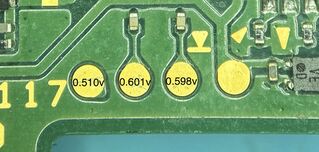
* Next pull the board out and on the opposite of the backlight connector there will be test points as seen in Figure 3. Set your multimeter to diode mode and place the red probe on ground and use your black probe to test each of the test points labeled in Figure 3. If any of the readings are off by more than 0.200v that will confirm a problem with the backlight IC or one of the capacitors around the backlight IC.
* [[File:DDDFB133-3764-46E2-B95D-2A806FA4B9A8 1 201 a.jpg|thumb|319x319px|Figure 3. Backlight test points on the opposite side of where the backlight connector is on Nintendo Switch]]Next pull the board out and on the opposite of the backlight connector there will be test points as seen in Figure 3. Set your multimeter to diode mode and place the red probe on ground and use your black probe to test each of the test points labeled in Figure 3. If any of the readings are off by more than 0.200v that will confirm a problem with the backlight IC or one of the capacitors around the backlight IC.
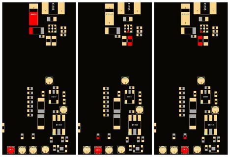
*These 3 test points correspond to lines in the backlight circuit that are all needed for the backlight to function normally. See photos below to see where each line goes. These points will also connect to 3 of the 4 pins on the backlight connector with the 4th being ground.
*These 3 test points correspond to lines in the backlight circuit that are all needed for the backlight to function normally. See Figure 4 to see where each line goes. These points will also connect to 3 of the 4 pins on the backlight connector with the 4th being ground.
*If the line you test bad is reading low or shorted then you will want to check for shorted components or corrosion around the components highlighted in Figure 4.[[File:Screenshot-From-2025-08-20-12-16(2).jpg|thumb|468x468px|Figure 4. Nintendo Switch backlight test points showing the components they connect to]]
*If the line reads as OL or a very high reading then you likely have a broken trace or corroded pad under the backlight IC. If the leftmost test point is reading as OL or abnormal you could also have a bad diode.
*It is common for corrosion from liquid damage shorting out or eroding the pads below the backlight IC so if you have abnormal readings and no shorted components around the backlight IC or you have removed/replaced the faulty components around the IC you may have to either try to reball it, or replace the IC
[[File:Switch backlight example img.jpg|left|thumb|Figure 5. Example of a bad backlight due to a line being corroded under the backlight IC. ]]
In Figure 5 we can see an example of what a backlight IC repair looks like. In this example the middle test point tested as OL. Liquid damage and corrosion caused the line to become broken. In order to fix it a jumper wire needed to be run from the pad under the backlight IC to the pad below it and the backlight IC needed to be reballed and soldered back onto the board. After repairing this broken line the backlight was again working on the Switch.
Revision as of 20:24, 20 August 2025
Nintendo Switch No Backlight
Device
Affects part(s)
Needs equipment
Difficulty
Type
This article is a stub. You can help Repair Wiki grow by expanding it
Nintendo Switch with no backlight on the LCD. The Switch will boot up and make noise, respond to touch or button inputs but LCD seems like it's not working unless you shine a light on it.
Symptoms
Figure 1. Front side of Nintendo Switch motherboard with the LCD connector circled in red and the backlight connector circled in blue
Switch will power on and make noise, respond to touch or button inputs but screen seems to not work
When shining a light on the display at the right angle you'll be able to see that the LCD is working just without a backlight, when testing with a light the easiest thing to see in order to confirm a bad backlight is the Nintendo logo when Switch is first booting up.
Solution
The problem is going to be related to either the LCD itself or the LCD circuit.
Figure 2. Back side of Nintendo switch motherboard showing locations of backlight circuit points of interest with the backlight IC circled in red and test points circled in blueFirst you will want to test with a known good LCD. You can dry fit a working LCD without removing the original by either just the bottom backlight cable or dry fitting both the LCD ribbon and backlight ribbon. See Figure 1 for reference on the locations of these connectors
If just the backlight ribbon is plugged in and the backlight circuit is working you should notice a slighter brighter screen when Switch is turned on, if the backlight circuit is bad then there will be no difference in the brightness of the screen
If you want to test with the backlight and LCD ribbon plugged in you will have to bend the LCD cable a bit to test without fully installing it. If you do this be very careful to not bend the LCD cable too much as it is pretty fragile and can easily rip and ruin your known good LCD
If you test with a known good LCD and still aren't getting a working backlight then your problem is going to be related to the backlight circuit.
First check the backlight connector for damage or loose pins
Figure 3. Backlight test points on the opposite side of where the backlight connector is on Nintendo SwitchNext pull the board out and on the opposite of the backlight connector there will be test points as seen in Figure 3. Set your multimeter to diode mode and place the red probe on ground and use your black probe to test each of the test points labeled in Figure 3. If any of the readings are off by more than 0.200v that will confirm a problem with the backlight IC or one of the capacitors around the backlight IC.
These 3 test points correspond to lines in the backlight circuit that are all needed for the backlight to function normally. See Figure 4 to see where each line goes. These points will also connect to 3 of the 4 pins on the backlight connector with the 4th being ground.
If the line you test bad is reading low or shorted then you will want to check for shorted components or corrosion around the components highlighted in Figure 4.Figure 4. Nintendo Switch backlight test points showing the components they connect to
If the line reads as OL or a very high reading then you likely have a broken trace or corroded pad under the backlight IC. If the leftmost test point is reading as OL or abnormal you could also have a bad diode.
It is common for corrosion from liquid damage shorting out or eroding the pads below the backlight IC so if you have abnormal readings and no shorted components around the backlight IC or you have removed/replaced the faulty components around the IC you may have to either try to reball it, or replace the IC
Figure 5. Example of a bad backlight due to a line being corroded under the backlight IC.
In Figure 5 we can see an example of what a backlight IC repair looks like. In this example the middle test point tested as OL. Liquid damage and corrosion caused the line to become broken. In order to fix it a jumper wire needed to be run from the pad under the backlight IC to the pad below it and the backlight IC needed to be reballed and soldered back onto the board. After repairing this broken line the backlight was again working on the Switch.


.jpg)
