Showing below up to 500 results in range #1 to #500.
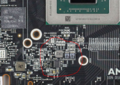
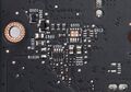
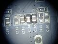
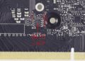
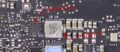
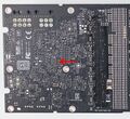
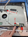
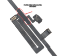
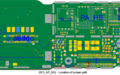
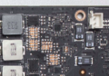
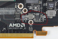 0.75 navi location.png 1,073 × 714; 1.56 MB
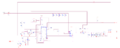
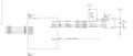
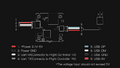
 0.75v en navi.png 1,215 × 241; 16 KB
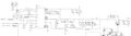
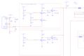
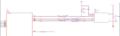
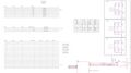
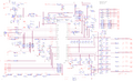
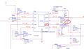
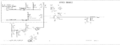
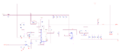 0.75v navi schematic.png 2,396 × 1,029; 111 KB
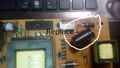 0019.jpg 666 × 375; 62 KB
 0x180000.png 894 × 650; 238 KB
 0x41 Panic Log.png 1,920 × 1,613; 4.8 MB
 0xc0000-paniclog.png 1,019 × 899; 1.34 MB
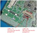
 1.8V en on navi.png 1,681 × 690; 45 KB
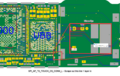
 1.8V on navi.png 1,131 × 798; 1.95 MB
 1.8V rail schematic Pascal.jpg 1,868 × 521; 119 KB
 1.8V schematic on navi.png 2,321 × 924; 110 KB
 1.8v being used in the GPU core.jpg 936 × 730; 66 KB
 1.8v enable polaris.jpg 1,606 × 1,082; 128 KB
 1.8v location on the board at the back .jpg 706 × 496; 97 KB
 1.8v powering the bios chip on pascal GPUs.jpg 1,385 × 590; 59 KB
 1.8v shorts pascal.jpg 2,560 × 1,047; 643 KB
 1024px-LAN9514 marked.jpg 1,024 × 778; 209 KB
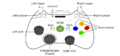
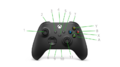
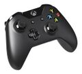 1024px-Microsoft-Xbox-One-controller.jpg 1,024 × 930; 107 KB
 1041px-Right Joycon DC-DC converter.jpg 1,041 × 899; 173 KB
 1070 hotplug circuit.png 1,696 × 1,282; 3.27 MB
 1070 hotplug schematic.png 2,389 × 747; 104 KB
 1070 q33.png 676 × 990; 1.45 MB
 1070 q33 location.png 545 × 633; 728 KB
 1200px-Joycon DCDC cap diagram.jpg 1,200 × 718; 116 KB
 1200px-Left Joycon DC-DC converter.jpg 1,200 × 750; 176 KB
 1200px-PAM2306 implementation schematic.png 1,200 × 610; 107 KB
 12v bus shorts on navi.png 4,764 × 1,972; 15.96 MB
 12v coupler burned.jpg 2,233 × 2,258; 1.51 MB
 12v ext shorts on navi.png 4,764 × 1,972; 15.96 MB
 14PM-Gyro.png 1,204 × 1,763; 607 KB
 14PM-Gyro2.png 1,204 × 1,763; 617 KB
 1663076592545.jpg 800 × 1,646; 115 KB
 1663076592575.jpg 800 × 1,646; 171 KB
 1LW4052295 03-dfc16541ba3c4105aae70154ab0ba988.jpg 1,500 × 1,000; 85 KB
 200px-Xboxseriess.jpg 200 × 238; 5 KB
 20200924 163333-e1602705255905.webp 2,000 × 1,035; 159 KB
 20230824 163906.jpg 2,153 × 1,614; 857 KB
 20230824 163918.jpg 2,106 × 1,580; 840 KB
 20230824 164003.jpg 2,375 × 1,782; 756 KB
 20230824 164023.jpg 2,110 × 1,582; 866 KB
 20230824 164412.jpg 1,841 × 1,381; 833 KB
 20230824 164431.jpg 2,189 × 1,642; 1.08 MB
 20230824 164441.jpg 2,068 × 1,551; 1.12 MB
 20230824 164516.jpg 2,386 × 1,790; 1.04 MB
 20230824 164532.jpg 1,940 × 1,455; 836 KB
 20230824 164546.jpg 1,743 × 1,308; 804 KB
 20230824 164603.jpg 1,777 × 1,333; 828 KB
 20230824 164742.jpg 1,794 × 1,346; 813 KB
 20230824 165330.jpg 1,703 × 1,277; 870 KB
 20230824 165346.jpg 1,755 × 1,316; 899 KB
 20230824 165349.jpg 1,842 × 1,381; 910 KB
 20230824 165352.jpg 1,898 × 1,423; 878 KB
 20230824 165355.jpg 1,858 × 1,393; 873 KB
 20230824 165407.jpg 2,100 × 1,575; 1.06 MB
 20230824 165426.jpg 2,191 × 1,644; 1.09 MB
 20230824 165439.jpg 1,895 × 1,421; 878 KB
 20230824 165442.jpg 1,868 × 1,401; 865 KB
 20230824 165505.jpg 1,644 × 1,233; 891 KB
 20230824 165512.jpg 1,652 × 1,239; 876 KB
 20230824 165516.jpg 1,708 × 1,281; 827 KB
 20230824 165524.jpg 2,305 × 1,729; 1.05 MB
 20230824 165556.jpg 2,366 × 1,775; 1.05 MB
 20230824 165605.jpg 2,087 × 1,565; 1,001 KB
 20230824 165614.jpg 2,205 × 1,654; 1.09 MB
 20230824 165633.jpg 2,125 × 1,594; 1.1 MB
 20230824 165639.jpg 2,423 × 1,817; 1.03 MB
 20240305 182709.jpg 1,376 × 1,834; 1.23 MB
 20240410 104859.jpg 1,628 × 1,223; 651 KB
 20240410 111249.jpg 2,320 × 1,740; 1.06 MB
 20240410 1155411.jpg 1,684 × 1,263; 1 MB
 2060 memory example.jpg 1,280 × 1,269; 353 KB
 2080 bios.png 839 × 599; 168 KB
 2080 bios schematic.png 1,262 × 376; 46 KB
 2080 crystal oscillator location.jpg 1,268 × 857; 537 KB
 2080 pex GS9216 schematic.png 1,302 × 558; 172 KB
 2080 pex en.png 1,103 × 505; 32 KB
 2080 pex mp schematic.png 1,292 × 764; 96 KB
 2080 pex on board.png 892 × 386; 937 KB
 2080 straps location on board.jpg 944 × 647; 295 KB
 2080 straps schematic.jpg 2,081 × 1,167; 224 KB
 2080 up1666q circuit.jpg 1,722 × 890; 174 KB
 2080 up9512S pinout.jpg 889 × 735; 102 KB
 2080 up9529 pinout.jpg 1,724 × 951; 222 KB
 2080 vcore enable.png 2,356 × 652; 154 KB
 2080 vcore on board.jpg 1,380 × 1,266; 1.61 MB
 2080 vcore schematic up9512p.png 2,307 × 1,396; 838 KB
 2080 vcore schematic up9512s.png 2,498 × 1,389; 321 KB
 2080 vmem circuit on board.jpg 1,291 × 769; 376 KB
 2080 vmem en.jpg 1,712 × 702; 81 KB
 2080 vmem up9512 schematic.png 1,920 × 1,221; 615 KB
 225px-Testmode.png 225 × 300; 109 KB
 225px-Testmode2.png 225 × 300; 65 KB
 2560px-HDZero Goggle RF Board L Back.jpg 2,560 × 2,238; 543 KB
 2560px-HDZero Goggle RF Board L Front.jpg 2,560 × 2,216; 631 KB
 2560px-HDZero Goggle RF Board R Back.jpg 2,560 × 2,490; 515 KB
 2560px-HDZero Goggle RF Board R Front-2048x1926.jpg 2,048 × 1,926; 430 KB
 2880px-HDZero Goggle IO Board L Back-scaled.jpg 2,560 × 1,437; 411 KB
 2880px-HDZero Goggle IO Board L Front-scaled.jpg 2,560 × 1,437; 455 KB
 2880px-HDZero Goggle IO Board R Back-scaled.jpg 2,560 × 1,437; 314 KB
 2880px-HDZero Goggle IO Board R Front-scaled.jpg 2,560 × 1,437; 430 KB
 2880px-HDZero Goggle Main PCB Board Back-scaled.jpg 2,560 × 732; 297 KB
 2880px-HDZero Goggle Main PCB Board Front-scaled.jpg 2,560 × 691; 293 KB
 2b249f08-4c8a-430c-8696-b5afa8cc4994.png 794 × 445; 93 KB
 2e674e0e-7efa-4ca0-a4f5-dae85a1b946b 1.8023a02ba5576e0b600cdc729f3faa38.webp 1,000 × 1,000; 37 KB
 3.3v shorts on navi.png 4,764 × 1,972; 15.96 MB
 300px-M92T36 CPU Capacitor.png 300 × 323; 191 KB
 300px-Model.png 300 × 85; 42 KB
 300px-PAM2306.jpg 300 × 240; 21 KB
 300px-Ps3 analog.jpg 300 × 169; 12 KB
 300px-Wireless Adapter for Windows.jpg 300 × 169; 3 KB
 300px-Wireless Gaming Receiver for Windows.jpg 300 × 226; 10 KB
 300px-Xbox-360-Controller-Black.png 300 × 246; 60 KB
 300px-Xbox Elite Wireless Controller.png 300 × 304; 56 KB
 300px-Xbox Elite Wireless Controller 2.png 300 × 284; 78 KB
 30a3f9c9-7e75-42b3-b4c1-161ae856c6ad.jpg 794 × 445; 72 KB
 350px-Ps3 analog.jpg 350 × 197; 15 KB
 359191833.jpg 450 × 600; 29 KB
 360 controller.png 1,024 × 474; 83 KB
 450px-CPU capacitor next to the SOT-323 IC near MAX17050.jpg 450 × 253; 21 KB
 450px-Nintendo Switch Fan Pinout.jpg 450 × 253; 32 KB
 450px-PAM2306 Raspberry Pi 2 v1.1.jpg 450 × 343; 42 KB
 450px-PAM2306 Raspberry Pi Zero.jpg 450 × 343; 43 KB
 4610-1NR ThermHead1.jpg 1,757 × 2,177; 906 KB
 4610-1NR ThermHead2.jpg 1,836 × 3,264; 1.5 MB
 4610-1NR ThermHead3.jpg 1,827 × 1,437; 541 KB
 4610-1NR ThermHead4.jpg 2,305 × 1,211; 502 KB
 4610-1NR ThermHead5.jpg 2,633 × 1,773; 1.15 MB
 480 pcb labeled back.jpg 2,560 × 1,613; 956 KB
 480 pcb labeled front.jpg 2,560 × 1,527; 904 KB
 48px-Information.png 48 × 48; 3 KB
 4a5a376a-50b3-444c-813d-248d4f82b51c.png 794 × 445; 100 KB
 5057g power.jpg 225 × 225; 8 KB
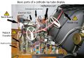 517px-CRT diagram.jpg 517 × 362; 49 KB
 51NzfmMfprL. SL1000 (1).jpg 1,000 × 1,000; 41 KB
 51NzfmMfprL. SL1000 .jpg 1,000 × 1,000; 41 KB
 5V on Navi.png 935 × 518; 1,020 KB
 5V rail on Pascal GPUs.jpg 1,142 × 650; 235 KB
 5V rail on pascal cards.jpg 1,861 × 624; 100 KB
 5V schematic on Navi.png 1,463 × 728; 129 KB
 5v enable turing.jpg 1,775 × 520; 73 KB
 5v turing board.jpg 927 × 571; 181 KB
 5v turing schematic.jpg 1,920 × 1,248; 146 KB
 5v vcc example 1.jpg 924 × 548; 78 KB
 5v vcc example 2.jpg 848 × 606; 60 KB
 600px-Nintendo-Switch-Console-Docked-wJoyConRB.jpg 600 × 343; 17 KB
 600px-PAM2306 PWM ok.png 600 × 360; 92 KB
 600px-PAM2306 current limiting.png 600 × 360; 68 KB
 6198FXoTAFL. SL1300 .jpg 1,300 × 1,300; 94 KB
 768px-MXL7704 I2C interface.jpg 768 × 599; 92 KB
 781px-HDZero Goggles Image.webp.png 781 × 586; 209 KB
 7e6d4367-dc96-48ed-b793-11fc5375f3d1.jpg 794 × 445; 50 KB
 889842057997.webp 1,200 × 1,200; 57 KB
 8P-WiFi-Jumpers.png 1,507 × 1,147; 1.88 MB
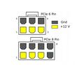 8 and 6 pin PCI-E connectors.jpg 677 × 524; 31 KB
 900px-Lu2a0371 6.jpg 900 × 900; 19 KB
 900px-Walksnail Avatar VTX.webp.png 900 × 506; 296 KB
 A2588ConnectorsOverview.png 2,640 × 3,861; 11.45 MB
 A2588FrontCameraFPCDiode.jpg 1,132 × 1,480; 719 KB
 A2588LeftAmbientLightSensorFPCDiode.jpg 1,200 × 1,521; 693 KB
 A2588LowerDigitizerFPCDiode.jpg 1,000 × 2,212; 822 KB
 A2588PowerButtonFPCDiode.jpg 618 × 1,046; 321 KB
 A2588RearCameraConnector.jpg 650 × 1,226; 389 KB
 A2588UpperDigitizerFPCDiode.jpg 558 × 1,216; 298 KB
 A2588VolumeConnectorDiode.png 1,504 × 2,344; 4.59 MB
 A2588 iPad Air 5 top mic connector diode readings.jpg 1,572 × 1,500; 886 KB
 ALS Sticker.png 1,482 × 1,397; 1,011 KB
 AVATAR WHOOP WIREING .webp 1,920 × 1,080; 51 KB
 A picture of a acer aspire v3-772g bios chip.png 686 × 391; 494 KB
 Acer Aspire v3-772g picture of the power button connector.png 1,092 × 521; 1.05 MB
 Air3 diode.jpg 2,121 × 1,610; 251 KB
 Air3 working.jpg 1,177 × 1,329; 112 KB
 Air5LCDFPCDiode.jpg 1,152 × 2,412; 1,024 KB
 Air 3 backlight filters.jpg 1,907 × 1,506; 252 KB
 Apple Ipad 10th InternalView.jpg 1,735 × 1,600; 639 KB
 Arrow.png 11 × 12; 187 bytes
 Artosyn AR8211 RF Chipset.jpg 1,225 × 1,015; 103 KB
 Artosyn AR9201 RF Chipset.jpg 326 × 328; 62 KB
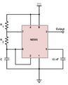 Astable-555-circuit.webp 441 × 547; 4 KB
 Asus A75V-K75V Fig. 2.jpg 1,889 × 932; 315 KB
 Asus A75V-K75V figure 1.jpg 1,199 × 585; 108 KB
 Asus L406M.jpg 1,100 × 900; 116 KB
 Avatar-HD-Bottom-Fan-scaled.jpg 2,560 × 1,920; 777 KB
 Avatar-HD-Front-PC-2-scaled.jpg 2,560 × 1,920; 784 KB
 Avatar-HD-Front-PCB-1-scaled.jpg 2,560 × 1,920; 739 KB
 Avatar-HD-HDMI-Board-scaled.jpg 1,920 × 2,560; 976 KB
 Avatar-HD-Optics-Oled-Connector-scaled.jpg 1,920 × 2,560; 834 KB
 Avatar-HD-X-Power-Board-2-scaled.jpg 1,920 × 2,560; 1.02 MB
 Avatar-HD-X-Power-Board-scaled.jpg 1,920 × 2,560; 1.04 MB
 Avatar-Optics-OLED-scaled.jpg 1,920 × 2,560; 1.06 MB
 Avatar HD Firmware Atrosyn.png 1,353 × 726; 753 KB
 Avatar HD Firmware Atrosyn (1).png 1,353 × 726; 753 KB
 Avatar HD Race VTX PCB Top.jpg 3,004 × 2,958; 596 KB
 Avatar HD VRX Stock Image.jpg 550 × 550; 33 KB
 Avatar Race.webp 1,200 × 800; 37 KB
 Avatar Race VTX PCB Bottom.jpg 2,253 × 2,154; 1.03 MB
 Avatar VRX BEC 2.jpg 1,920 × 1,374; 337 KB
 Avatar VRX Internal PCB Top.jpg 2,560 × 1,099; 402 KB
 Avatar VRX Module Cover Removed.jpg 1,920 × 1,539; 326 KB
 Avatar VRX RF Front End.jpg 2,560 × 1,437; 523 KB
 Avatar VRX SOC.jpg 2,560 × 1,437; 584 KB
 Avatar VRX Under Bec.jpg 2,560 × 1,437; 358 KB
 Avatar VTX 5V Regulator.jpg 6,000 × 3,368; 1.83 MB
 Avatar VTX Dialog DA9062.jpg 2,270 × 1,406; 643 KB
 Avatar VTX USB Pinout.jpg 5,184 × 2,920; 1.8 MB
 Avatar VTX Uart Repair.jpg 2,612 × 1,457; 682 KB
 Avatar Whoop 1S VTX Bottom.jpg 2,766 × 2,618; 1.71 MB
 Avatar Whoop 1S VTX Top.jpg 2,480 × 2,608; 1.8 MB
 Avatar Whoop VTX.webp 800 × 800; 15 KB
 Avatar Whoop VTX Bottom Testing.jpg 5,184 × 2,920; 1.63 MB
 Avatar Whoop VTX Top Testing.jpg 3,857 × 3,349; 1.62 MB
 BCM2711 Pi4 chip 700.jpg 700 × 619; 469 KB
 BCM54213 Gigabit ethernet controller 700.jpg 700 × 576; 401 KB
 BDM-010.jpg 800 × 800; 139 KB
 BDM010.png 754 × 644; 721 KB
 BWE-UART-Pinout.jpg 2,200 × 1,472; 1.58 MB
 Back 5V shorts on pascal GPUs.jpg 2,560 × 1,072; 699 KB
 Bad probing.png 800 × 480; 66 KB
 Batch image upload.png 1,867 × 700; 20 KB
 Bbpmu jumpers.png 1,044 × 1,303; 940 KB
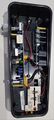
 Behringer HB01 01.jpg 2,218 × 1,638; 776 KB
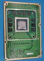
 Behringer HB01 02.jpg 2,118 × 1,638; 675 KB
 Behringer HB01 03.jpg 1,638 × 3,651; 1.65 MB
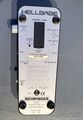 Behringer HB01 BottomView.jpg 1,638 × 2,374; 1.18 MB
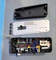 Behringer HB01 Takeapart.jpg 1,586 × 1,687; 666 KB
 Board 1 - side 1.jpg 1,637 × 2,292; 1.16 MB
 Board 2 side 1.jpg 1,638 × 2,421; 1.39 MB
 Board 3 - side 1.jpg 1,638 × 2,525; 1.23 MB
 Bq24780s.png 450 × 253; 227 KB
 CECHL04 PCB 01.jpg 3,968 × 2,976; 2.83 MB
 CECHL04 PCB 02.jpg 2,976 × 3,968; 2.83 MB
 CRT magnet damage.jpg 5,184 × 3,888; 1.91 MB
 CUH-10xxA - SAA-001 - GL3520.png 2,198 × 1,007; 4.28 MB
 CaddX Avatar PCB Front 0.jpg 4,725 × 2,196; 1.73 MB
 Caddx FPV Goggles V1.webp 1,100 × 1,100; 20 KB
 Cameras.jpg 1,920 × 2,560; 1.43 MB
 Capacitor filters.jpg 958 × 411; 30 KB
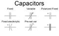 Capacitor symbols.jpg 582 × 366; 36 KB
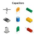
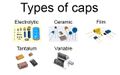 Capacitor types.jpg 582 × 366; 50 KB
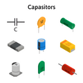 Capacitor types packages.png 2,404 × 2,404; 995 KB
 Capacitor types packagess.jpg 2,404 × 2,404; 149 KB
 Cd828ec4-f77b-4a44-b10b-e8c837b09f63.jpg 794 × 445; 48 KB
 Charging Port Flex Panic Log.png 1,137 × 1,571; 3.31 MB
 Charging Port flex diagram.png 1,132 × 1,829; 3.75 MB
 Chat pad and headset with box.jpg 1,200 × 1,200; 86 KB
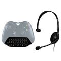 Chat pad and headset with controller.jpg 1,000 × 1,000; 64 KB
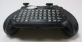 Chat pad bottom view.jpg 1,200 × 623; 69 KB
 ComputerAllInOnes.jpg 1,920 × 1,280; 201 KB
 Computer components.jpg 1,920 × 1,280; 251 KB
 Corrosion10.jpg 1,734 × 1,082; 431 KB
 Corrosion11.jpg 1,920 × 1,426; 255 KB
 Corrosion13 spelled out.jpg 1,741 × 1,565; 620 KB
 Corrosion14 labeled.jpg 1,920 × 1,520; 345 KB
 Corrosion15labeled.jpg 1,920 × 1,323; 296 KB
 Corrosionqfnpointedout.jpg 2,194 × 1,295; 228 KB
 Cracked capacitor.png 1,024 × 569; 918 KB
 Create page.png 1,817 × 944; 92 KB
 Create page button.png 1,557 × 1,049; 109 KB
 DVR PCB Back-2048x1294.jpg 2,048 × 1,294; 352 KB
 DVR PCB Front-2048x1194.jpg 2,048 × 1,194; 415 KB
 Damaged ALS Sensor on iPad Pro.png 2,521 × 1,235; 3.96 MB
 Dead 1080ti core.jpg 1,577 × 1,182; 775 KB
 Diode-bridge-rectifier.jpg 2,358 × 1,285; 146 KB
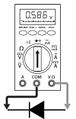 Diode measurement.jpg 397 × 624; 54 KB
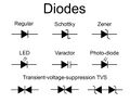 Diode schematic symbols.jpg 1,500 × 1,186; 93 KB
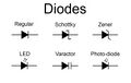 Diode symbols.jpg 1,500 × 944; 67 KB
 Diode types packages.png 2,404 × 2,400; 1.14 MB
 Dustgate small pic.png 647 × 618; 238 KB
 E9a371be-275f-4526-bdb3-8a09e068f61a 1.ddea9b1d9921f5a73cac3540745cd0d8.webp 1,500 × 1,500; 105 KB
 Edit semantics button.png 953 × 194; 22 KB
 Elite2Inline2.png 1,080 × 833; 370 KB
 Elite 2 chat pad back.jpg 2,708 × 2,105; 778 KB
 Elite 2 chat pad back without back paddles.jpg 474 × 363; 20 KB
 Epson ELPDC21 document camera.jpg 3,023 × 1,434; 1.86 MB
 Epson elpdc21 document camera I2c scl sda.jpg 3,024 × 2,160; 1.42 MB
 Epson elpdc21 document camera main cpu reset signal.jpg 2,416 × 2,092; 1.57 MB
 Epson elpdc21 document camera mainboard bottom.jpg 3,843 × 1,956; 1.74 MB
 Epson elpdc21 document camera mainboard top.jpg 3,520 × 2,364; 3.58 MB
 Epson elpdc21 document camera pcb camera head.jpg 3,352 × 2,436; 2.46 MB
 Epson elpdc21 document camera power button signal.jpg 2,416 × 1,971; 1.47 MB
 Epson elpdc21 document camera power button signal.png 2,416 × 1,971; 7.97 MB
 Epson elpdc21 document camera power rails measured.jpg 3,759 × 2,374; 1.74 MB
 Epson elpdc21 document camera power rails measured zoomed in on two regulators.jpg 2,190 × 1,817; 1.4 MB
 Epson elpdc21 document camera reseat this connector.jpg 3,352 × 2,436; 1.28 MB
 Epson elpdc21 document camera reseat this connector first.jpg 1,609 × 1,080; 488 KB
 Epson elpdc21 document camera spi pins found.jpg 4,032 × 2,268; 1,004 KB
 Epson elpdc21 document camera uart signals.jpg 2,267 × 2,051; 1.61 MB
 Epson elpdc21 document camera what the traces look like under the thine chip.jpg 8,000 × 6,000; 5.38 MB
 Error Code 2162-0002.webp 4,000 × 2,250; 362 KB
 Error Code 2162-0002 -2.jpeg 1,785 × 966; 315 KB
 Example Cut for Face ID.png 1,367 × 827; 192 KB
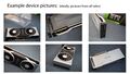 Example device pictures.jpg 1,920 × 1,080; 299 KB
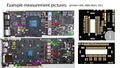 Example measurement pictures.jpg 1,920 × 1,080; 517 KB
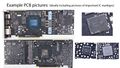 Example pcb pictures.jpg 1,920 × 1,080; 533 KB
 Expansion-card-for-xbox-no-cap-1000x1000.png 1,000 × 1,000; 234 KB
 Fat Shark Avatar PCB Front RF.jpg 5,184 × 3,888; 1.93 MB
 Fat Shark Avatar PCB Front RF 1.jpg 3,024 × 4,032; 1.76 MB
 Fat Shark Avatar PWR PCB Back.jpg 3,024 × 2,864; 1.39 MB
 Fat Shark Avatar PWR PCB Front.jpg 2,992 × 3,114; 1.67 MB
 Fat Shark Dominator HD FPV Goggles.png 768 × 453; 213 KB
 Fat Shark Scout HD Antenna-2048x1536.jpg 2,048 × 1,536; 213 KB
 Fat Shark Scout HD Antenna Side-scaled.jpg 2,560 × 1,920; 496 KB
 Fat Shark Scout HD Fan-2048x1536.jpg 2,048 × 1,536; 357 KB
 Fat Shark Scout HD Lens-2048x1536.jpg 2,048 × 1,536; 282 KB
 Fat Shark Scout HD Top PCB-2048x1536.jpg 2,048 × 1,536; 507 KB
 Fat Shark Scout HD Top PCB 1-2048x1536.jpg 2,048 × 1,536; 323 KB
 Fat shark Avatar Goggles PCB Back.jpg 5,183 × 2,297; 1.84 MB
 Fat shark Avatar Goggles PCB Back ROM.jpg 5,184 × 3,243; 1.36 MB
 Fat shark Avatar Goggles PCB SOC.jpg 3,024 × 4,032; 1.68 MB
 Fat shark scout hd goggles.jpg 1,000 × 1,000; 60 KB
 Fatshark Avatar Goggles PCB Front Main.jpg 4,747 × 1,993; 1.57 MB
 Fatshark Avatar Goggles PCB Front Shield.jpg 5,184 × 2,134; 1.58 MB
 Fatshark Avatar Goggles PCB SOC.jpg 5,184 × 3,888; 1.58 MB
 Fatshark Avatar Goggles RAM.jpg 3,024 × 4,032; 1.64 MB
 Finally. Xbox one headset adaptor.jpg 1,024 × 1,024; 82 KB
 FindFlashMediaAndKeepout.jpg 1,280 × 1,498; 128 KB
 Flash capacitor.jpg 662 × 496; 49 KB
 Front 3.3 short pascal.jpg 2,560 × 1,047; 644 KB
 Front 5V shorts on pascal GPUs.jpg 2,560 × 1,047; 657 KB
 GOggles-X-VRX-Module-Bottom-scaled.jpg 2,560 × 1,437; 395 KB
 GP102 1.8V Short.jpg 1,280 × 960; 541 KB
 GP104 1.8V Short.jpg 450 × 338; 22 KB
 GTX 1080.jpg 2,560 × 1,047; 655 KB
 Galaxy S10 AUX PORT CONNECTOR.jpg 843 × 877; 183 KB
 Galaxy S10 BATTERY CONNECTOR - Diode Mode Readings.jpg 1,280 × 1,296; 142 KB
 Galaxy S10 SCREEN CONNECTOR - Diode Mode Readings.jpg 1,280 × 1,346; 230 KB
 Galaxy S10 SELFIE CAMERA - Diode Mode Readings.jpg 706 × 704; 76 KB
 Galaxy S10 TELEPHOTO+WIDE - Diode Mode Readings.jpg 318 × 704; 52 KB
 Galaxy S10 ULTRAWIDE CONNECTOR - Diode Mode Readings.jpg 789 × 704; 77 KB
 Game consoles.jpg 1,920 × 1,280; 234 KB
 Gigabyte 1080Ti location of AND gate.jpg 1,529 × 1,147; 1,003 KB
 Goggles-X-Face-Plate-Removed.png 3,840 × 2,160; 7.42 MB
 Goggles-X-Module-Cover-and-Heatsink-Removed-scaled.jpg 2,560 × 1,437; 552 KB
 Goggles-X-Top-Shell-Removed.png 3,840 × 2,160; 8.88 MB
 Goggles-X-VRX-Module-scaled.jpg 2,560 × 1,437; 403 KB
 Goggles-X-top-Cover-Removed.png 3,840 × 2,160; 8.41 MB
 Goggles X.jpeg 1,157 × 685; 68 KB
 Gtx 1070 hot plug detection circuit.png 1,696 × 1,282; 3.27 MB
 Gtx 1080 error 43.jpg 1,185 × 800; 95 KB
 HDZero V4 DVR PCB Back-2048x904.jpg 2,048 × 904; 317 KB
 HDZero V4 RF PCB Back-2048x843.jpg 2,048 × 843; 254 KB
 HDZero VRX Fuse Blown-2048x1194.jpg 2,048 × 1,194; 417 KB
 HDZero VRX Module-2048x1152.jpg 2,048 × 1,152; 100 KB
 HDZero VRX V4 DVR PCB Front-2048x909.jpg 2,048 × 909; 283 KB
 HDZero VRX V4 RF PCB Front-2048x922.jpg 2,048 × 922; 227 KB
 HTC Vive Pro Disassembled.jpg 2,081 × 1,242; 615 KB
 HTC Vive Pro FrontView.jpg 1,457 × 1,456; 422 KB
 HTC Vive Pro Main FrontView.jpg 1,411 × 1,451; 411 KB
 HTC Vive Pro Main LensView.jpg 1,647 × 1,638; 448 KB
 HTC Vive Pro USB.jpg 1,635 × 1,634; 538 KB
 HTC Vive Pro WithoutGasket.jpg 1,638 × 1,705; 473 KB
 Hanns-G HG-281DPB.jpg 474 × 355; 18 KB
 Hanns-G HG-281DPB Back.jpg 474 × 355; 17 KB
 Hanns-G HG-281DPB Bottom.jpg 474 × 355; 10 KB
 Hanns-G HG-281DPB Front.jpg 640 × 480; 24 KB
 Hanns-G HG281D Back.jpg 550 × 412; 15 KB
 Hanns-G HG281D Front.jpg 550 × 412; 16 KB
 Hanns-G HG281D board.jpg 1,280 × 720; 156 KB
 Hanns-G HG281D board1.jpg 814 × 627; 207 KB
 Hanns G HG281D side-buttons 93j4.1024.webp 600 × 503; 12 KB
 IP7 C12 D12 Jumpers.jpg 1,732 × 1,435; 515 KB
 IP7 C12 D12 UV Mask.png 1,251 × 668; 1.81 MB
 IP7 Grayed Out Speaker Icon.png 496 × 420; 445 KB
 IP7 No Backlight.png 744 × 1,131; 1.81 MB
 IP7 No Touch Fix.jpg 1,906 × 1,423; 1.22 MB
 IP7 Screen Home Button Flex.png 637 × 955; 534 KB
 IP7 Voice Memo App.png 669 × 1,282; 1.85 MB
 IPad 6 Power Button Component Values.png 700 × 410; 81 KB
 IPad Air 4 - Charging Port Diode Mode Readings.jpg 2,162 × 3,842; 698 KB
 IPad Pro 11in 4th Gen - CD3217.png 1,411 × 1,219; 2.51 MB
 IPad Pro 11in 4th Gen - Charging Properly.png 1,449 × 1,084; 1.91 MB
 IPad Pro 11in 4th Gen - Not Charging.png 789 × 780; 577 KB
 IPad Pro 129 3rd charging port connector diode readings.jpg 1,232 × 2,352; 1.04 MB
 IPad Pro 129 5th Gen LCD diode mode readings 1.jpg 873 × 1,605; 836 KB
 IPad Pro 129 5th Gen LCD diode mode readings 2.jpg 933 × 1,461; 726 KB
 IPad Pro 129 5th Gen LCD diode mode readings 3.jpg 1,017 × 1,953; 918 KB
 IPad Pro 129 5th Gen LCD diode mode readings 4.jpg 1,032 × 1,887; 852 KB
 IPad Pro 129 5th Gen charging port diode readings.jpg 885 × 1,422; 705 KB
 IPad Pro 129 5th gen board overview.jpg 2,252 × 4,000; 2.33 MB
 IPad Pro No Face ID.png 1,920 × 1,459; 2.06 MB
 IPad Pro Top Flex Diagram.png 1,448 × 827; 219 KB
 IPad Pro Top Flex Diagram 2.png 1,383 × 827; 207 KB
 IPhone12PM Jumper Solution for Stuck In Recovery Mode.png 1,776 × 1,487; 2.8 MB
 IPhone 12 Pro Max Power Button Connector with Water Damage.png 1,100 × 1,185; 1.89 MB
 IPhone 13 Panic Log List.png 300 × 203; 63 KB
 IPhone 13 Pro Max - SMC PANIC - ASSERTION FAILED.png 300 × 226; 108 KB
 IPhone 13 Pro Max - SMC PANIC - ASSERTION FAILED - 0x800.png 300 × 183; 115 KB
 IPhone 13 Pro Max - SMC PANIC - ASSERTION FAILED 0x1000.png 980 × 737; 726 KB
 IPhone 13 Pro Max - SMC PANIC - ASSERTION FAILED 0x800.png 933 × 568; 709 KB
 IPhone 14 Pro and Pro Max Board ID Resistor.png 1,437 × 742; 322 KB
 IPhone 14 panic log 0x100000.png 1,026 × 765; 138 KB
 IPhone 14 panic log 0x100000 Charging Port.png 871 × 1,277; 2.15 MB
 IPhone 14 panic log 0x200000.png 1,026 × 765; 135 KB
 IPhone 14 panic log 0x200000 Prox Flex.png 875 × 1,304; 1.7 MB
 IPhone 14 panic log 0x400000.png 1,928 × 1,084; 3.76 MB
 IPhone 14 panic log Example 0x400000.png 1,026 × 765; 142 KB
 IPhone 15 Pro Max - Battery issue.png 1,782 × 1,811; 5.08 MB
 IPhone 15 Pro Max - Wireless flex diagram.png 2,426 × 1,215; 5.23 MB
 IPhone 15 Sandwich.jpg 2,252 × 2,482; 827 KB
 IPhone 4S Jumper on R61.png 1,280 × 1,220; 2.55 MB
 IPhone 4s Missing R61.png 1,807 × 1,414; 2.46 MB
 IPhone 7 Plus RAM Short.jpg 1,126 × 2,000; 235 KB
 IPhone 8 Mosfet.jpg 1,080 × 1,035; 774 KB
 IPhone SE 2020 - No Touch Long Jumper path.png 2,560 × 904; 1.47 MB
 IPhone SE 2020 - R6610 I2C1 AP SCL Jumper Path.png 2,560 × 1,417; 2.35 MB
 IPhone SE 2020 C6456 Jumper Location.png 2,560 × 1,606; 1.2 MB
 IPhone SE 2020 C6466 Jumper Location & path.png 2,560 × 1,093; 699 KB
 IPhone SE 2020 No Touch.png 1,808 × 1,145; 621 KB
 IPhone SE 2020 R6611 Jumper Location.png 2,560 × 1,269; 2 MB
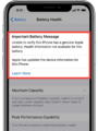 Important Battery Message - iPhone.png 1,012 × 1,345; 458 KB
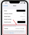 Important Camera Message - iPhone.png 991 × 1,197; 325 KB
 Important Display Message- iPhone.png 1,276 × 496; 352 KB
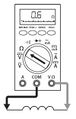 Inductor measurement.jpg 397 × 624; 54 KB
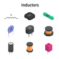 Inductor types.png 2,400 × 2,404; 1.07 MB
 Information.png 48 × 48; 3 KB
 Input area asus zenbook.png 450 × 253; 184 KB
 Inspection1.jpg 1,920 × 1,485; 463 KB
 Inspection2.jpg 2,560 × 1,442; 589 KB
 Inspection3.jpg 800 × 1,354; 167 KB
 Inspection41.jpg 661 × 822; 39 KB
 Inspection5.jpg 1,041 × 897; 95 KB
 Ip7Coils.jpg 645 × 600; 107 KB
 Ipadair3backlight.jpg 1,255 × 1,066; 105 KB
 KDL-40W2000 blown fuse.jpeg 1,096 × 1,461; 1.11 MB
 LA-8321P backlight power.jpg 1,309 × 789; 83 KB
 LAN9514 marked.jpg 1,367 × 1,039; 755 KB
 LM1117 on 580 xfx.jpg 2,120 × 1,590; 1.09 MB
 Laptops.jpg 1,920 × 1,281; 410 KB
 Lenovo Hard=Drive Password Prompt.jpg 800 × 600; 122 KB
 Lenovo Power-On, Supervisor, or System Management password prompt.jpg 864 × 600; 152 KB
 Location of PEX rail on a Zotac GTX 1080Ti (Figure 1).jpg 1,897 × 1,423; 1.05 MB
 MXL7704.webp 600 × 600; 29 KB
 MXL7704 location.webp 600 × 337; 245 KB
 Mats example.jpg 1,712 × 1,175; 270 KB
 Micron 4GB RAM chip 700.jpg 700 × 512; 452 KB
 Microsoft-xbox-next-720 1369193238 1200 1200 overflow.jpg 1,200 × 1,200; 52 KB
 Model.jpg 1,600 × 1,200; 550 KB
 Navi Measurement.png 4,764 × 1,972; 15.85 MB
 Navi perst buf schematic.png 1,298 × 560; 36 KB
 Neck Board CRT Diagram.jpg 4,032 × 3,024; 1.29 MB
 New guide example.png 1,580 × 1,140; 229 KB
 Nintendo-Super-Famicom-SNES.png 4,560 × 2,370; 3.4 MB
 Nintendo-Switch-Blue-Screen.jpg 1,200 × 700; 119 KB
 Nintendo-Switch-Orange-Screen.jpg 1,024 × 597; 56 KB
 Nintendo DS Lite.jpg 3,615 × 2,761; 5.1 MB
 Nintendo DS Lite Bottom LCD Back Side.jpg 4,500 × 3,000; 5.44 MB
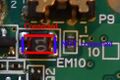 Nintendo DS Lite EM10 check.jpg 488 × 325; 23 KB
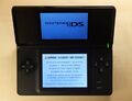
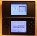 Nintendo DS Lite Main Menu.jpg 2,937 × 2,867; 5.23 MB
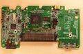
 Nintendo DS Lite PCB Bottom.jpg 4,300 × 2,500; 5.58 MB
 Nintendo DS Lite PCB Bottom Game-Slot Removed.jpg 4,000 × 2,630; 6.72 MB
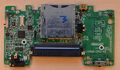
 Nintendo DS Lite PCB Bottom annotated.jpg 4,300 × 2,500; 1.52 MB
 Nintendo DS Lite PCB Top.jpg 4,400 × 2,933; 1.24 MB
 Nintendo DS Lite PCB top side with lcd.jpg 5,800 × 3,867; 9.9 MB
 Nintendo DS Lite bottom.jpg 3,393 × 2,000; 3.51 MB
 Nintendo Switch Diode Mode Readings Mechanic T824.jpg 1,889 × 1,889; 320 KB
 Nvidia memory labeling pascal.jpg 984 × 887; 296 KB
 Old guide example.png 1,413 × 308; 24 KB
 PAL-SNES Schematic page-0001.jpg 9,934 × 7,017; 11.41 MB
 PCIe Slot Pinout.jpg 870 × 1,042; 213 KB
 PERSTb schematic view.jpg 1,771 × 583; 82 KB
 PEX rail under the microscope on a Zotac GTX 1080Ti.jpg 1,919 × 1,439; 1.05 MB
 PEX rail usage on Pascal GPUs.jpg 1,262 × 861; 162 KB
 PMIC + PCH A1990.png 800 × 599; 475 KB
 PS4Pro-HDMI-Mechnic-Readings.jpg 1,636 × 2,181; 561 KB
 PS4ProNORDumpWithUARTEnabled.jpg 1,348 × 736; 404 KB
 PS4Slim-HDMI-Mechnic-Readings.jpg 1,636 × 2,181; 559 KB
 PS4SlimRAMBlocks.jpg 478 × 466; 59 KB
 PS4WeeToolsFailedMemoryTest.png 1,070 × 300; 41 KB
 PS4WeeToolsGoodNORDump.png 1,348 × 736; 21 KB
 PS4WeeToolsMemoryTestFlag.jpg 1,348 × 766; 314 KB
 PS4WeeToolsValidatedNOR.png 1,348 × 766; 36 KB
 PS5-HDMI-Mechnic-Readings.jpg 1,636 × 2,181; 555 KB
 Panic Log Example of 0x400000.png 1,822 × 1,932; 5.29 MB
 Panic Log List.png 1,987 × 1,344; 987 KB
 Panic Log List ipad 4.png 1,920 × 1,299; 999 KB
 Panic Log Prs0.png 1,404 × 1,033; 860 KB
 Panic Log Prs0 iphone x.jpg 1,404 × 1,033; 198 KB
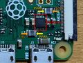
 Parts-of-R-Pi-3B.webp 1,024 × 694; 63 KB
 Pascal Bios board.jpg 1,827 × 1,089; 467 KB
 Pascal Bios schematic.png 2,174 × 1,067; 177 KB
 Pascal Vcore controller location.jpg 1,306 × 1,073; 446 KB
 Pascal Vcore enable schematic .png 2,145 × 808; 173 KB
 Pascal Vmem controller on pcb.png 935 × 651; 1.44 MB
 Pascal crystal oscillator .jpg 1,373 × 1,184; 458 KB
 Pavilion 22xi Back.jpg 1,200 × 1,200; 62 KB
 Pavilion 22xi Front.jpg 1,200 × 951; 66 KB
 Pex rail location on pascal.jpg 891 × 657; 149 KB
 Pex schematic pascal.jpg 1,644 × 582; 111 KB
 Phones.jpg 1,920 × 1,280; 349 KB
 Pi1 Back.jpg 4,032 × 3,024; 5 MB
 Pi1 front1.jpg 4,032 × 3,024; 5.32 MB
 Pi3B HDMI Circuit.jpg 508 × 408; 70 KB
 Pi3B Wifi Antenna.jpg 1,300 × 639; 133 KB
 Pi3 1500.jpg 1,500 × 993; 1.23 MB
 Pi4B power circuitry 700.jpg 700 × 490; 366 KB
 Pi4B underside 700-1.jpg 699 × 465; 372 KB
 Pi4B wifi module Proant antenna 1500.jpg 1,500 × 1,093; 1.02 MB
 Piccoloissue.jpg 1,024 × 576; 93 KB
 Picture.png 826 × 548; 911 KB
 Picture2.png 754 × 494; 877 KB
 Picture of Neoprogrammer discovering possible bios.png 785 × 524; 40 KB


.jpg)


.jpg)


.png)