(+Manufacturer, release year) |
No edit summary |
||
| (20 intermediate revisions by the same user not shown) | |||
| Line 1: | Line 1: | ||
{{Device page | {{Device page | ||
|Manufacturer=Epson|Device | |Manufacturer=Epson | ||
|Has code name=H757MA_R2 2176136 | |||
|Device type=Camera | |||
}} | |||
At the moment this page only describes the mainboard called H757MA_R2 2176136. It is not known if other revisions exist or not. | |||
==Guides== | ==Guides== | ||
| Line 8: | Line 12: | ||
==Device pictures== | ==Device pictures== | ||
<gallery showthumbnails="1"> | <gallery showthumbnails="1"> | ||
File: | File:Epson ELPDC21 document camera.jpg|The device - seen from above. | ||
</gallery> | </gallery> | ||
==PCB pictures== | ==PCB pictures== | ||
<gallery showthumbnails="1"> | <gallery showthumbnails="1"> | ||
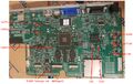
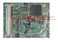
File: | File:Epson elpdc21 document camera mainboard top.jpg|Main board - top side | ||
File:Epson elpdc21 document camera mainboard bottom.jpg|Main board - bottom side | |||
File:Epson elpdc21 document camera pcb camera head.jpg|PCB in camera head | |||
</gallery> | </gallery> | ||
==Reference measurements (also schematics if available)== | ==Reference measurements (also schematics if available)== | ||
<gallery showthumbnails="1"> | <gallery showthumbnails="1"> | ||
File: | File:Epson elpdc21 document camera power rails measured.jpg|Voltages measured on a working unit | ||
File:Epson elpdc21 document camera power rails measured zoomed in on two regulators.jpg|Measured voltages - Zoomed in on two smaller regulators | |||
File:Epson elpdc21 document camera uart signals.jpg|Uart Signals | |||
File:Epson elpdc21 document camera spi pins found.jpg|SPI communication pins between main CPU and Thine ISP chip | |||
File:Epson elpdc21 document camera power button signal.jpg|The power button signal | |||
File:Epson elpdc21 document camera main cpu reset signal.jpg|Main CPU (SoC) reset signal | |||
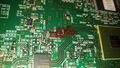
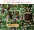
File:Epson elpdc21 document camera what the traces look like under the thine chip.jpg|Under the THP7321 | |||
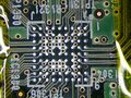
File:THP7312 bottom substrate.JPG|Bottom of the THP7312 | |||
File:Epson elpdc21 document camera I2c scl sda.jpg|I2C SCL and SDA lines | |||
</gallery> | </gallery> | ||
==More Information/External Sources== | ==More Information/External Sources== | ||
=== Voltages measured on working product (after turning on) === | |||
{| class="wikitable" | |||
|+ | |||
!Component RefDes | |||
!Voltage | |||
!Type | |||
|- | |||
|C2008/C2011/L2000 | |||
|5.15V | |||
|Switching | |||
|- | |||
|C1911/C1912/L1903 | |||
|3.3V | |||
|Switching | |||
|- | |||
|C2012/L2001 | |||
|1.2V | |||
|Switching | |||
|- | |||
|C1905/L1901 | |||
|1.35V | |||
|Switching | |||
|- | |||
|C1910/C1922/L1902 | |||
|1.42V | |||
|Switching | |||
|- | |||
|C1904/L1900 | |||
|3.0V | |||
|Switching | |||
|- | |||
|C2003/IC2000 | |||
|3.3V | |||
|Linear | |||
|- | |||
|C2009/IC2003 | |||
|1.8V | |||
|Linear | |||
|- | |||
|C1804/IC1800 | |||
|3.33V | |||
|Linear, Always On | |||
|} | |||
=== Partial BOM === | |||
{| class="wikitable" | |||
|+ | |||
!Component RefDes | |||
!Marking | |||
!Name | |||
!Comment | |||
|- | |||
|IC2002, IC1903, IC2004, IC1901, IC1902, IC1900 | |||
|QTZ | |||
|TPS62140RGTR/TPS62140RGTT | |||
|Step-down converter | |||
|- | |||
|IC2000 | |||
|NR1 | |||
|TLV70033DSER/TLV70033DSET | |||
|3.3V linear regulator | |||
|- | |||
|IC2003 | |||
|NK1 | |||
|TLV70018DSER/TLV70018DSET | |||
|1.8V linear regulator | |||
|- | |||
|IC1800 | |||
|LPBG | |||
|LP2981-33 | |||
|3.3V linear regulator | |||
|- | |||
|IC1600, IC1603 | |||
|G8Y | |||
|S-80928CNNB-G8YT2x | |||
|2.8V Voltage detector with delay (IC1600 resets the main CPU, IC1603 resets the smaller microcontroller IC1000) | |||
|- | |||
|IC1000 | |||
|C17W04F10J | |||
|Epson S1C17W04 | |||
|16-bit Microcontroller, Always On | |||
|- | |||
|IC900 | |||
| | |||
|Hynix H27U4G8_6F2D / H27S4G8_6F2D | |||
|Nand Flash | |||
|- | |||
|IC1300 | |||
|THP7312 | |||
|THine THP7312 | |||
|ISP chip | |||
|- | |||
|IC1 | |||
|MCIMX6D5EYM10AD | |||
|IMX6DQCEC | |||
|Main CPU: i.MX 6Dual/6Quad Applications Processors for Consumer Products | |||
|- | |||
|C205 | |||
| | |||
|220nF | |||
|Author replaced mechanically damaged component, not sure about correctness of this measurement, but product worked with replacement. | |||
|- | |||
|C272 | |||
| | |||
|100nF | |||
|Author replaced mechanically damaged component, not sure about correctness of this measurement, but product worked with replacement. | |||
|- | |||
|R209 | |||
| | |||
|9.1 ohm | |||
|Author replaced mechanically damaged component, not sure about correctness of this measurement, but product worked with replacement. | |||
|- | |||
|R353 | |||
| | |||
|0 ohm link | |||
|Author replaced mechanically damaged component, not sure about correctness of this measurement, but product worked with replacement. | |||
|} | |||
=== Useful Signals === | |||
{| class="wikitable" | |||
|+ | |||
!Component | |||
!Pin # | |||
!Name | |||
!Comment | |||
|- | |||
|CN1600 | |||
|7 | |||
|UART_TX | |||
|(TX from the board's perspective, runs at 460800 bps) | |||
|- | |||
|CN1600 | |||
|9 | |||
|UART_RX | |||
| | |||
|- | |||
|CN1300 | |||
|10 | |||
|I2C_SCL | |||
|I2C line is shared by devices on the motherboard, but also goes to the camera head | |||
|- | |||
|CN1300 | |||
|11 | |||
|I2C_SDA | |||
| | |||
|- | |||
|IC1600 | |||
|4 | |||
|Reset of the main CPU | |||
|Short this to ground to cause a main CPU reboot. (this is an open drain output of the voltage detector, so it's okay to short to ground) | |||
|- | |||
|CN2001/CN1000* | |||
|2 | |||
|Power Button | |||
|Short this to ground to prompt the board to boot even when the flex cable to the interface board is not connected | |||
|} | |||
<nowiki>*</nowiki> not clear from the silk screen, please see images above | |||
Latest revision as of 01:43, 27 January 2024
| Epson ELPDC21 | |
|---|---|
| Manufacturer | Epson |
| Code name | H757MA_R2 2176136 |
| Release date | |
| Device type | Camera |
At the moment this page only describes the mainboard called H757MA_R2 2176136. It is not known if other revisions exist or not.
Guides
Explanatory Guides
| Type | Difficulty | |
|---|---|---|
| Epson ELPDC21 Debugging UART | Troubleshooting/Diagnostics | 3. Hard |
Repair Guides
| Affects part | Type | Difficulty | |
|---|---|---|---|
| Epson ELPDC21 Not turning on, led blinking | Connectors | Teardown | 2. Medium |
Device pictures
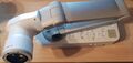
The device - seen from above.

PCB pictures
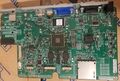
Main board - top side
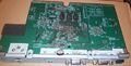
Main board - bottom side
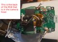
PCB in camera head


Reference measurements (also schematics if available)
Voltages measured on a working unit
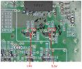
Measured voltages - Zoomed in on two smaller regulators
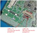
Uart Signals
SPI communication pins between main CPU and Thine ISP chip

The power button signal
Main CPU (SoC) reset signal
Under the THP7321
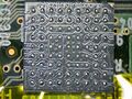
Bottom of the THP7312
I2C SCL and SDA lines


More Information/External Sources
Voltages measured on working product (after turning on)
| Component RefDes | Voltage | Type |
|---|---|---|
| C2008/C2011/L2000 | 5.15V | Switching |
| C1911/C1912/L1903 | 3.3V | Switching |
| C2012/L2001 | 1.2V | Switching |
| C1905/L1901 | 1.35V | Switching |
| C1910/C1922/L1902 | 1.42V | Switching |
| C1904/L1900 | 3.0V | Switching |
| C2003/IC2000 | 3.3V | Linear |
| C2009/IC2003 | 1.8V | Linear |
| C1804/IC1800 | 3.33V | Linear, Always On |
Partial BOM
| Component RefDes | Marking | Name | Comment |
|---|---|---|---|
| IC2002, IC1903, IC2004, IC1901, IC1902, IC1900 | QTZ | TPS62140RGTR/TPS62140RGTT | Step-down converter |
| IC2000 | NR1 | TLV70033DSER/TLV70033DSET | 3.3V linear regulator |
| IC2003 | NK1 | TLV70018DSER/TLV70018DSET | 1.8V linear regulator |
| IC1800 | LPBG | LP2981-33 | 3.3V linear regulator |
| IC1600, IC1603 | G8Y | S-80928CNNB-G8YT2x | 2.8V Voltage detector with delay (IC1600 resets the main CPU, IC1603 resets the smaller microcontroller IC1000) |
| IC1000 | C17W04F10J | Epson S1C17W04 | 16-bit Microcontroller, Always On |
| IC900 | Hynix H27U4G8_6F2D / H27S4G8_6F2D | Nand Flash | |
| IC1300 | THP7312 | THine THP7312 | ISP chip |
| IC1 | MCIMX6D5EYM10AD | IMX6DQCEC | Main CPU: i.MX 6Dual/6Quad Applications Processors for Consumer Products |
| C205 | 220nF | Author replaced mechanically damaged component, not sure about correctness of this measurement, but product worked with replacement. | |
| C272 | 100nF | Author replaced mechanically damaged component, not sure about correctness of this measurement, but product worked with replacement. | |
| R209 | 9.1 ohm | Author replaced mechanically damaged component, not sure about correctness of this measurement, but product worked with replacement. | |
| R353 | 0 ohm link | Author replaced mechanically damaged component, not sure about correctness of this measurement, but product worked with replacement. |
Useful Signals
| Component | Pin # | Name | Comment |
|---|---|---|---|
| CN1600 | 7 | UART_TX | (TX from the board's perspective, runs at 460800 bps) |
| CN1600 | 9 | UART_RX | |
| CN1300 | 10 | I2C_SCL | I2C line is shared by devices on the motherboard, but also goes to the camera head |
| CN1300 | 11 | I2C_SDA | |
| IC1600 | 4 | Reset of the main CPU | Short this to ground to cause a main CPU reboot. (this is an open drain output of the voltage detector, so it's okay to short to ground) |
| CN2001/CN1000* | 2 | Power Button | Short this to ground to prompt the board to boot even when the flex cable to the interface board is not connected |
* not clear from the silk screen, please see images above