More actions
| Nikon D850 shows battery error despite known-good battery | |
|---|---|
| Device | Nikon D850 |
| Affects part(s) | Main board or DC-in board |
| Needs equipment | Fine screwdriver set, basic oscilloscope, multimeter, hot air station |
| Difficulty | ◉◉◌◌ Medium |
| Type | Soldering, Part replacement |
This article is a stub. You can help Repair Wiki grow by expanding it
Problem description
When inserting a battery into the camera, the monochrome LCD shows only the battery symbol, at first with a charging animation, then empty. When flipping the power switch, the LCD backlight turns on, but no other information appears on any screen and the empty battery symbol begins flashing.
Symptoms
No other behavior can be provoked by pressing any combination of controls, including the factory reset combination (hold QUAL and exposure control for 2 seconds).
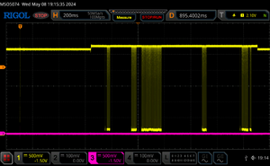
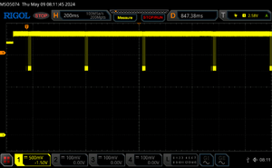
When probing the battery contacts during insertion, data may be observed appearing on the onewire bus on the center contact or it may be absent. In this particular case, there was data on the bus but the logic levels were invalid.
Solution
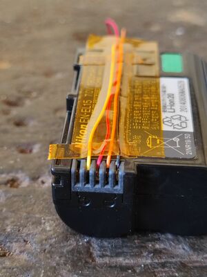
Confirm the battery handshake fails
To increase confidence without opening the camera, use thin wires to break out the GND and middle battery contacts. Covering the wires in kapton prevents them from being pulled out. Observe the voltage on the middle contact with an oscilloscope while inserting the battery. Bursts of data should be readily apparent with 0-3.3V logic levels at a 200ms time base for 1-2 seconds after insertion. If there are repeated short burts of data with identical length, communication is failing. If there are bursts of varying length and with good logic levels, communication is working and the fault may be elsewhere.
Trace the onewire bus
Remove the back cover of the camera to access the main board. This video may help you keep track of screws: https://www.youtube.com/watch?v=ehffG0t_MTM
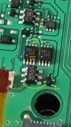
See https://nikonrumors.com/wp-content/uploads/2017/09/Nikon-D850-DSLR-camera-teardown-5.jpg for an overview of the D850 main board. The close-up shot in this article is of the chips just to the left of the black main screen flex cable.
The large flex connector in the bottom right corner includes the battery onewire contact near the middle. Expect a 100 Ohm resistance between the flex connector and the middle battery contact. This resistor is on the DC-in board which contains the battery contacts.
From the flex connector, expect continuity to a patch of small ICs in the bottom left corner, specifically to pin 3 of the left bus switch, which is a SSOP-8 component labeled "WLC 335". If this group of ICs are working properly, expect the following measurements:
- Continuity between pin 2 and 5 of the bus switch and pin 2 of the unidentified SOT23-6 chip below it
- High impedance between pins 2 and 3 of the bus switch
- High impedance between pins 2, 3, 5, 6 and Vcc or GND
- Continuity between pin 3 of the SOT23 chip and the drain of the small P-channel MOSFET to its right
- A 3.3V idle level with bursts of data pulling LOW on the gate of the MOSFET (labeled "To CPU")
- 0V with bursts pulling HIGH (3.3V) on the drain of the MOSFET and pin 3 of the SOT23
- 3.3V with bursts pulling LOW (0V) on SOT23 pin 2 and bus switch pins 2, 3 and 5.
In this particular case, the bus switch failed with a low resistance between +3.3V and pins 2 and 3 as well as a constant resistance of ~120 Ohm between pins 2 and 3. This fault prevented devices on the onewire bus to pull the data line down to a valid LOW level. Removing the switch and bridging pins 2 and 3 was sufficient to allow the camera to boot with an internal battery.
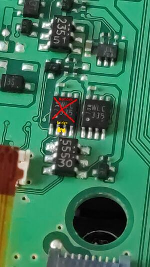
The bus switch's model number is TC7WBL3305CFK. The part is available at all major electronic parts dealers.
