More actions
| Thinkpad T490 Bios Password Removal | |
|---|---|
| Device | Thinkpad T490 |
| Affects part(s) | MEC1633 |
| Needs equipment | Soldering Iron; Glasgow Interface Explorer (or other EC programmer), Screwdrivers, Spudgers |
| Difficulty | ◉◉◉◌ Hard |
| Type | Soldering, Software |
This article is a stub. You can help Repair Wiki grow by expanding it
Problem description
This guide describes how to remove a Power-On / Supervisor / System Management Password that the laptop might ask for during boot, or while entering setup.
This guide does not apply to hard-drive passwords.


Symptoms
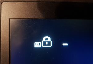
- The screen shows the BIOS password icon (Figure 1)
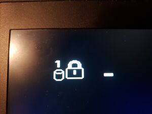
- The screen must not show the HDD password icon (Figure 2)
Solution
What you need
- Screwdrivers to open up the laptop, and take out the motherboard
- Spudgers to get the bottom case clips to release
- Hot air, two soldering irons, or soldering tweezers, and the skills to safely move an 0201 size resistor
- Some wires to be soldered to the unpopulated JTAG footprint on the bottom of the board
- A tool that can program the MEC1663 EC chip, for example the open hardware Glasgow Interface Explorer, but proprietary alternatives also exist
Repair Steps
- Attempt to enter the bios with an empty password, and if successful, you may get partial access to the BIOS settings, take a screenshot of the main screen showing various serial numbers.
- Take off the bottom cover
- Disconnect and remove the main battery
- Disconnect the CMOS battery
- You have to fully take out the motherboard, because the necessary pads are on the other side:
- Disconnect the trackpad ribbon cable on the trackpad side
- Remove the trackpad screws
- Remove the mouse button keycaps
- Underneath the mouse button keycaps unscrew the screws holding the keyboard assembly in place
- Slide the keyboard assembly towards the screen, and tilt it up
- Gently disconnect the keyboard assembly flex cables from the motherboard
- Disconnect any remaining connectors from the motherboard
- Remove the IO bracket screws, and any other screws holding the motherboard in
- Keep the cooling system screws in. They do not interfere with taking out the motherboard, and we will need to reprogram the EC while the laptop is powered, so it's safer to leave the cooling system on the board. (Also keep the cooling system plugged in)
- Beware that the thin heat-pipe is very fragile, and it can barely hold the weight of the fan. Do not apply any unnecessary force to it, or it will be crushed.
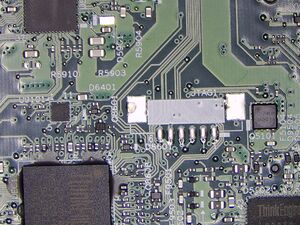
- Take out the motherboard. We will be working with the area shown in Figure 3.
- Move the TRST resistor from pull-down to pull-up position. See Figure 4 for exact placement.
- Solder wires to the JTAG pins. See Figure 5 for the pinout. Note that with Glasgow Interface Explorer you don't need to worry about the exact pinout, because the tool can auto-detect it for you, just make sure you get the GND pin right, and that you solder a wire to all other pins except for pin 6.
- Connect the motherboard to a charger
- Use your EC programmer tool to manipulate the EEPROM, to remove the password. (See following section for details)
- Disconnect the charger
- Restore the TRST resistor to its pull-down configuration, and remove the jtag wires
- When reassembling the laptop make sure that reconnecting the battery is the last step taken.
- If you have cleared the EEPROM completely, then you will have to restore the laptop serial numbers. In this case use ThinkPad Serial Number Update Utility.
- Initialize the EEPROM
- Assign UUID
- Set system identification
- Add "C0" S/N data. The long form serial number should be concatenated from: "1S", the "Type" on the bottom sticker, and the Serial Number on the bottom sticker, without dash symbols or date codes
- Example: the bottom sticker says "TYPE 20N3-012345 S/N PF-678901", then the input code should be "1S20N3012345PF678901"
- Add "B0" S/N data. The long form board serial number should be printed on a sticker on the motherboard, right under the RAM slot cover, it's written in small font. The long form board serial number should look like this: "8SSBxxxxxxxxL1HFxxxxxxx". The second half of it should match the board serial number as may have been seen previously in the bios.
- Add "C0" S/N data. The long form serial number should be concatenated from: "1S", the "Type" on the bottom sticker, and the Serial Number on the bottom sticker, without dash symbols or date codes
