More actions
This article is a stub. You can help Repair Wiki grow by expanding it
| Micromaster 430 fault F0023 repair (faulty optocoupler) | |
|---|---|
| Device | |
| Affects part(s) | |
| Needs equipment | |
| Difficulty | |
| Type | |
Problem description
Diagnosing and fixing error/fault code F0023 on Siemens micromaster 430 inverter/VFD. This particular guide concerns a faulty driving optocoupler.


Symptoms
- Fault F0023 over 20Hz output frequency, "working" under 20Hz but choppy motor movement.
- When starting the motor on low frequency (below 10Hz), it spins, stops, then spins again
Solution
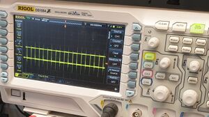
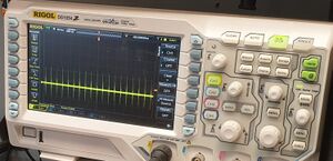
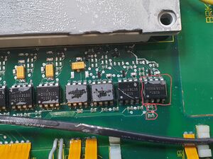
First, check if the IGBT module itself is functioning and not faulty, use an LCR meter and measure all 6 output gates against their respective emitters. If the IGBT is fine, measure the signal going to it while running, BE VERY CAREFUL! IF YOU SHORT SOMETHING WHILE MEASURING THE GATES WHEN THE INVERTER IS RUNNING IT COULD EXPLODE!. I recommend soldering thin enameled wires from the gates and emitters for ease of measurement. In this case, one of the gates was not being driven properly, (figures 2,3). Tracked where the driving signal is coming from, it was from the right most opto coupler. The output side was fine (every component measured correctly, resistors and the SOT23 diodes) but after measuring the input side (figure 4), both resistors (330 and 2.7k) were different values. Although even when replaced, the inverter still acted weird. Turns out, even though the optocoupler diode measured fine (1.4v drop on pin 2-3) the output side was faulty. Replacing the optocoupler fixed this issue.
