More actions
No edit summary |
No edit summary |
||
| Line 16: | Line 16: | ||
5V is a fairly simple rail that is usually the first to turn on. The controller is always ON, V<sub>CC</sub> should always be high if V<sub>IN</sub> is present. | 5V is a fairly simple rail that is usually the first to turn on. The controller is always ON, V<sub>CC</sub> should always be high if V<sub>IN</sub> is present. | ||
The enable signal is generated by a resistor divider, which means the controller should be always enabled, if EN is missing, it is either a faulty resistor or the controller is shorting EN to GND. | |||
==Usage== | ==Usage== | ||
Latest revision as of 11:39, 16 March 2024
| 5V Rail on Navi GPUs Explained | |
|---|---|
| Type | Circuit |
| Device(s) | RX 5700, RX 5700XT |
| Difficulty | ◉◉◌◌ Medium |
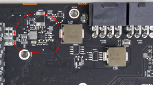
This page explains how the 5V rail is created and what it is used for in AMD's Navi (RX 5000) GPUs.


The controller Circuit
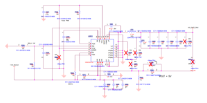
Navi cards usually uses a GS9230 or similar to step down 12V to 5V that is used to power different ICs found on the GPU.
There is no public datasheet for the GS9230 yet. However, the GS9238 has similar pin out which can be used for diagnosis.
Markings on the board and schematic may differ from one GPU vendor to another, however, the circuit is almost always the same.
5V is a fairly simple rail that is usually the first to turn on. The controller is always ON, VCC should always be high if VIN is present.
The enable signal is generated by a resistor divider, which means the controller should be always enabled, if EN is missing, it is either a faulty resistor or the controller is shorting EN to GND.
Usage
As the name suggests in the schematics, "5V_GATE_DRV" is almost exclusively used to power the smart power stages on the card. While on other generations 5V was used to power various ICs, on Navi that is rather rare as 3.3V is used instead.
PGOOD signal from this rail is not used to power the next rail. The rail is "independent", not required for other rails and does not require any other rail to turn on except the base rails.
Common Problems
Here are common problems for the 5V rail and how to fix them.
No voltage out on the 5 V rail
First thing to check is the EN signal which should be 2+ V followed by Vin which should be 12 V (Figure 2) if one of them is missing then check the schematic and follow the signal to find the culprit, it's usually a faulty resistor or in rare cases a cut trace.
After making sure both of the above are there, check the VCC pin. If there is no voltage on it then most likely the controller is faulty and needs changing.
Short on 5V rail
The only things that can short 5V rail is either a capacitor or a PowerStage. Simply apply Isopropyl alcohol on suspected shorted components and inject voltage on the rail to reveal the shorted component.
Low voltage on 5V
This usually only happens with a faulty controller or if there is a semi-short (sub 50 ohms) where a component is drawing too much current from the 5V rail above what it's rated for. Fixing this is the same as finding a short (because it most likely is).
If the rail is not shorted, then check the feedback circuit, replace the controller if the resistors measure fine.
