More actions
No edit summary |
|||
| (One intermediate revision by the same user not shown) | |||
| Line 4: | Line 4: | ||
|Device type=Camera | |Device type=Camera | ||
}} | }} | ||
At the moment this page only describes the mainboard called H757MA_R2 2176136. It is not known if other revisions exist or not. | At the moment this page only describes the mainboard called H757MA_R2 2176136. It is not known if other revisions exist or not. | ||
| Line 35: | Line 34: | ||
File:Epson elpdc21 document camera I2c scl sda.jpg|I2C SCL and SDA lines | File:Epson elpdc21 document camera I2c scl sda.jpg|I2C SCL and SDA lines | ||
</gallery> | </gallery> | ||
==More Information/External Sources== | |||
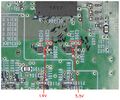
=== Voltages measured on working product (after turning on) === | === Voltages measured on working product (after turning on) === | ||
| Line 194: | Line 195: | ||
<nowiki>*</nowiki> not clear from the silk screen, please see images above | <nowiki>*</nowiki> not clear from the silk screen, please see images above | ||
Latest revision as of 01:43, 27 January 2024
| Epson ELPDC21 | |
|---|---|
| Manufacturer | Epson |
| Code name | H757MA_R2 2176136 |
| Release date | |
| Device type | Camera |
At the moment this page only describes the mainboard called H757MA_R2 2176136. It is not known if other revisions exist or not.
Guides
Explanatory Guides
| Type | Difficulty | |
|---|---|---|
| Epson ELPDC21 Debugging UART | Troubleshooting/Diagnostics | 3. Hard |
Repair Guides
Create a Guide
Device pictures
-
The device - seen from above.
PCB pictures
-
Main board - top side
-
Main board - bottom side
-
PCB in camera head
Reference measurements (also schematics if available)
-
Voltages measured on a working unit
-
Measured voltages - Zoomed in on two smaller regulators
-
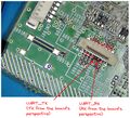
Uart Signals
-
SPI communication pins between main CPU and Thine ISP chip
-
The power button signal
-
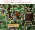
Main CPU (SoC) reset signal
-
Under the THP7321
-
Bottom of the THP7312
-
I2C SCL and SDA lines
More Information/External Sources
Voltages measured on working product (after turning on)
| Component RefDes | Voltage | Type |
|---|---|---|
| C2008/C2011/L2000 | 5.15V | Switching |
| C1911/C1912/L1903 | 3.3V | Switching |
| C2012/L2001 | 1.2V | Switching |
| C1905/L1901 | 1.35V | Switching |
| C1910/C1922/L1902 | 1.42V | Switching |
| C1904/L1900 | 3.0V | Switching |
| C2003/IC2000 | 3.3V | Linear |
| C2009/IC2003 | 1.8V | Linear |
| C1804/IC1800 | 3.33V | Linear, Always On |
Partial BOM
| Component RefDes | Marking | Name | Comment |
|---|---|---|---|
| IC2002, IC1903, IC2004, IC1901, IC1902, IC1900 | QTZ | TPS62140RGTR/TPS62140RGTT | Step-down converter |
| IC2000 | NR1 | TLV70033DSER/TLV70033DSET | 3.3V linear regulator |
| IC2003 | NK1 | TLV70018DSER/TLV70018DSET | 1.8V linear regulator |
| IC1800 | LPBG | LP2981-33 | 3.3V linear regulator |
| IC1600, IC1603 | G8Y | S-80928CNNB-G8YT2x | 2.8V Voltage detector with delay (IC1600 resets the main CPU, IC1603 resets the smaller microcontroller IC1000) |
| IC1000 | C17W04F10J | Epson S1C17W04 | 16-bit Microcontroller, Always On |
| IC900 | Hynix H27U4G8_6F2D / H27S4G8_6F2D | Nand Flash | |
| IC1300 | THP7312 | THine THP7312 | ISP chip |
| IC1 | MCIMX6D5EYM10AD | IMX6DQCEC | Main CPU: i.MX 6Dual/6Quad Applications Processors for Consumer Products |
| C205 | 220nF | Author replaced mechanically damaged component, not sure about correctness of this measurement, but product worked with replacement. | |
| C272 | 100nF | Author replaced mechanically damaged component, not sure about correctness of this measurement, but product worked with replacement. | |
| R209 | 9.1 ohm | Author replaced mechanically damaged component, not sure about correctness of this measurement, but product worked with replacement. | |
| R353 | 0 ohm link | Author replaced mechanically damaged component, not sure about correctness of this measurement, but product worked with replacement. |
Useful Signals
| Component | Pin # | Name | Comment |
|---|---|---|---|
| CN1600 | 7 | UART_TX | (TX from the board's perspective, runs at 460800 bps) |
| CN1600 | 9 | UART_RX | |
| CN1300 | 10 | I2C_SCL | I2C line is shared by devices on the motherboard, but also goes to the camera head |
| CN1300 | 11 | I2C_SDA | |
| IC1600 | 4 | Reset of the main CPU | Short this to ground to cause a main CPU reboot. (this is an open drain output of the voltage detector, so it's okay to short to ground) |
| CN2001/CN1000* | 2 | Power Button | Short this to ground to prompt the board to boot even when the flex cable to the interface board is not connected |
* not clear from the silk screen, please see images above


