GTX 1070 Random freezing/crashing fix, power hot plug detection fault: Difference between revisions
No edit summary |
MadEDoctor (talk | contribs) (I have added a schematic describing the other part of the detection circuit that also can fail and cause the same issue the post addresses. I've added some steps in the solution sections that might be helpful and also one more symptom for the same issue. And lastly, I fixed the numbering of the photos.) |
||
| Line 7: | Line 7: | ||
}} | }} | ||
==Problem description== | ==Problem description== | ||
This guide addresses a particular freezing issue related to GTX 1070s. It is important to note that this guide is not a universal solution for all freezing problems that you may encounter, but rather specifically addresses one of them related to PCIE external 8 pin hot plug detection. It is worth bearing in mind that freezing can have various underlying causes not just this.[[File:Gtx 1070 hot plug detection circuit.png|thumb|Hot plug detection circuit on the GTX 1070 (Figure 1) | This guide addresses a particular freezing issue related to GTX 1070s. It is important to note that this guide is not a universal solution for all freezing problems that you may encounter, but rather specifically addresses one of them related to PCIE external 8 pin hot plug detection. It is worth bearing in mind that freezing can have various underlying causes not just this.[[File:Gtx 1070 hot plug detection circuit.png|thumb|Hot plug detection circuit on the GTX 1070 (Figure 1)]][[File:1070 hotplug schematic.png|thumb|Hot-plug detection circuit schematic on GTX 1070 (Figure 2)]]This particular freezing problem is caused by the power connector hot plug detection circuitry (Figure 1&2) | ||
==Symptoms== | ==Symptoms== | ||
| Line 15: | Line 15: | ||
* All voltage rails are present have correct resistance values | * All voltage rails are present have correct resistance values | ||
* THERM_OVERT* signal goes low after the freeze | * THERM_OVERT* signal goes low after the freeze | ||
* You get the "Please power down and connect PCI-e power cable for this graphics card" screen even though the cable is plugged in. | |||
==Solution== | ==Solution== | ||
Verify the proper functioning of the NPN transistors Q509 and Q511, you can use a multimeter in diode mode. First, connect the red probe to pin 1 and the black probe to pin 2 of the transistors, and measure the voltage reading. The reading should fall between 500-750mV. If any of the readings fall outside of this range, replace the corresponding transistor(s). | Verify the proper functioning of the NPN transistors Q509 and Q511, you can use a multimeter in diode mode. First, connect the red probe to pin 1 and the black probe to pin 2 of the transistors, and measure the voltage reading. The reading should fall between 500-750mV. If any of the readings fall outside of this range, replace the corresponding transistor(s). | ||
[[File:1070 PEX input schematic.png|thumb|The second part of the hot-plug detection circuit "PEX input" (Figure 3)]] | |||
Verify the proper functioning of N-channel MOSFET Q510, begin by checking for any shorts. Using a multimeter, measure the resistance between the drain and source terminals of the MOSFET. The multimeter should show an open circuit, indicating that the MOSFET is not shorted. If the multimeter shows a low resistance, replace the MOSFET. To check if the MOSFET is working properly, remove it from the circuit and perform the following steps. Connect the black probe of the multimeter to pin 2 and the red probe to pin 1 briefly, then move the red probe to pin 3. The multimeter should show a very low resistance, similar to a short circuit. However, when you touch the MOSFET gate with your finger, the reading should return to normal. If the multimeter does not show a low resistance or the reading does not change when you touch the gate with your finger, it indicates that the MOSFET may not be functioning properly and needs to be replaced. | |||
[[File:1070 q33 location.png|thumb|168x168px|Location of Q33 on reference GTX 1070 (Figure 4)]] | |||
[[File:1070 q33.png|thumb|212x212px|Location of Q33 on MSI GTX 1070 GAMING X (Figure 5)<gallery> | |||
</gallery>]]After confirming that all of the above components are working properly, the cause could be an NPN transistor Q33 (Figure 4) on the front under the PCIE power connectors. | |||
In case you find no fault with the above mentioned circuit, you can also check the second part of the Hot-plug detection circuit (Figure 3). The physical location of the circuit is on the front right side usually in the middle or lower part of the board. | |||
If all the transistors measure fine, check the pull-up resistors as they tend to fail sometimes and be quite annoying to diagnose as the normal level on some lanes is "logic 1" (3.3 or 5V) which is provided via current limiting resistors like R219 and they are usually in the rage of 1-10kΩ ±500Ω. If the readings doesn't match with the schematics you will need to replace the given resistor. Please make sure when measuring resistances, that the card is not powered on! | |||
It is best if you have something like a CPU heatsink on hand so you can boot or try to boot the card while apart to be able to measure the voltages on these circuits. This can be especially helpful when the card doesn't even want to start (The PCI-e power is plugged in, but you still see the message to plug the cable/s whenever you try to boot the PC). | |||
Latest revision as of 21:32, 7 June 2024
| GTX 1070 Random freezing/crashing fix, power hot plug detection fault | |
|---|---|
| Device | GTX 1070 |
| Affects part(s) | Whole board |
| Needs equipment | multimeter, soldering iron, soldering station |
| Difficulty | ◉◉◉◌ Hard |
| Type | Soldering |
Problem description
This guide addresses a particular freezing issue related to GTX 1070s. It is important to note that this guide is not a universal solution for all freezing problems that you may encounter, but rather specifically addresses one of them related to PCIE external 8 pin hot plug detection. It is worth bearing in mind that freezing can have various underlying causes not just this.
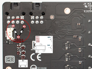
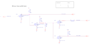
This particular freezing problem is caused by the power connector hot plug detection circuitry (Figure 1&2)
Symptoms
- Works for some time but freezes randomly
- Freezes all the time
- Freezes happen unrelated to load or temperature
- All voltage rails are present have correct resistance values
- THERM_OVERT* signal goes low after the freeze
- You get the "Please power down and connect PCI-e power cable for this graphics card" screen even though the cable is plugged in.
Solution
Verify the proper functioning of the NPN transistors Q509 and Q511, you can use a multimeter in diode mode. First, connect the red probe to pin 1 and the black probe to pin 2 of the transistors, and measure the voltage reading. The reading should fall between 500-750mV. If any of the readings fall outside of this range, replace the corresponding transistor(s).
Verify the proper functioning of N-channel MOSFET Q510, begin by checking for any shorts. Using a multimeter, measure the resistance between the drain and source terminals of the MOSFET. The multimeter should show an open circuit, indicating that the MOSFET is not shorted. If the multimeter shows a low resistance, replace the MOSFET. To check if the MOSFET is working properly, remove it from the circuit and perform the following steps. Connect the black probe of the multimeter to pin 2 and the red probe to pin 1 briefly, then move the red probe to pin 3. The multimeter should show a very low resistance, similar to a short circuit. However, when you touch the MOSFET gate with your finger, the reading should return to normal. If the multimeter does not show a low resistance or the reading does not change when you touch the gate with your finger, it indicates that the MOSFET may not be functioning properly and needs to be replaced.
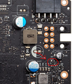
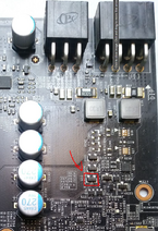
After confirming that all of the above components are working properly, the cause could be an NPN transistor Q33 (Figure 4) on the front under the PCIE power connectors.
In case you find no fault with the above mentioned circuit, you can also check the second part of the Hot-plug detection circuit (Figure 3). The physical location of the circuit is on the front right side usually in the middle or lower part of the board.
If all the transistors measure fine, check the pull-up resistors as they tend to fail sometimes and be quite annoying to diagnose as the normal level on some lanes is "logic 1" (3.3 or 5V) which is provided via current limiting resistors like R219 and they are usually in the rage of 1-10kΩ ±500Ω. If the readings doesn't match with the schematics you will need to replace the given resistor. Please make sure when measuring resistances, that the card is not powered on!
It is best if you have something like a CPU heatsink on hand so you can boot or try to boot the card while apart to be able to measure the voltages on these circuits. This can be especially helpful when the card doesn't even want to start (The PCI-e power is plugged in, but you still see the message to plug the cable/s whenever you try to boot the PC).


