More actions
| MacBook Pro A1297 Green light on charger, no boot repair | |
|---|---|
| Device | MacBook Pro A1297 |
| Affects part(s) | MCP AUXC Circuit |
| Needs equipment | Soldering and Rework Equipment, Screw Driver Set, Tweezers |
| Difficulty | ◉◉◉◌ Hard |
| Type | Soldering |
Problem description
2008 or 2009 Unibody A1297 MacBook Pro shows green light on charger but does not boot, Device has no liquid damage

Symptoms
- Device does not boot from battery or charger power
Solution
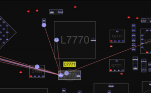
In most cases with a 2008 (820-2390) or 2009 (820-2610) Unibody 17 Inch MacBook Pro that doesn't boot when the device has no liquid or physical damage to the logic board this is caused by the tantalum cap @ C7771 failing.
Diagnostic Steps
Test C771 for 1.1v if C7771 is below 1.1v the cap is failing.
Repair Steps
This is a very easy repair but does require soldering so it's technically "hard" however even a beginner (Someone who has been practicing pulling caps off and soldering caps back onto donor boards, I do not mean someone who has never used a soldering iron) can attempt this repair with caution (obviously on their own board only) and should be able to succeed (You don't exactly need a microscope for this job but it's still nice to use if you have one). However still be careful with this repair as these logic boards are getting harder and harder to replace as the A1297 models are by far the rarest model of unibody MacBook Pro's and replacing this board can be costly, Also in the case of the Late 2008 and 2009 A1297 Unibody MacBook Pro's the case is physically different (port layout) from the later 2010 and 2011 models which means the price for these boards are high even if they are much more obsolete.
Before we start there is something important to take note of. In the case of C7771 failing this is due to a poor design decision on Apple's part, The small tantalum cap Apple used is to small for it's purpose (this cap is on a S5 rail and is always on) which is why it fails so regularly, You should use a bigger 330uf non tantalum cap in this area instead of replacing it with another small tantalum cap that will fail again. Due to the small area to work with in this location on the board and the small foot print for this component you may have to run a jumper wire to one side of the cap because a bigger cap may not fit properly on the original pads. You may also have to slightly move L7770 up to make space for the cap however in my experience I have been able to fit bigger cap's to these boards without moving L7770 and without running a jumper wire. This is all going to be down to the size of cap you use. This repair isn't pretty as you basically have to force something that's not intended to be there, to be there but this is the only way to correctly fix these boards to ensure they will not fail again.
As with replacing any big cap this is pretty standard.
1) Remove the cap
Apply some flux to the area, tin both sides of the cap with leaded solder to make it easier to remove, Apply hot air and remove the component, I use around 350-370c at 97 airspeed on my Quick 861DW for these kind of caps.
2) Solder the new cap
As I mentioned this part is going to depend on how big the cap you are replacing it with is. Drop it in the location to size it up. If it doesn't fit or is touching L7770, Apply some flux and using hot air and your tweezers move L7770 up so that it's still connected to it's pads but less in your way.
Once you have decided you have enough space or have made space, tin the pads and using hot air solder the cap down, in a lot cases you will only be able to solder it to one pad correctly, in that case it's better to solder to the left pad while moving the cap on a slight angle upwards to allow space on the right pad to run a jumper wire if needed. If you are lucky your cap will be able to solder in place just fine and be fully connected if not run a small jump from the right pad to the right side of the cap to fully connect it.
and done! the board should now boot! :) and you should not run into this issue again (Unless you used another tantalum cap that is). As I mentioned a beginner can attempt this repair and should be able to succeed (given they have enough practice) but I highly recommend they watch Louis's video on this issue first!
