| Visual Inspection - Repair Basics | |
|---|---|
| Type | Method |
| Device(s) | General |
| Difficulty | ◉◌◌◌ Easy |
This guide emphasizes the importance of visual inspection in logic board repairs, highlighting the significance of trusting your eyes before delving into complex problem-solving.
Trust Your Eyes!
Most of the time, your eyes are more important than your brain. Always inspect the edges of the logic board! Majority of the time, the problem is somewhere in that area.
There is no greater time-sink for the new technician than over-intellectualizing a problem. Trying to decode every signal abbreviation and reverse engineering undocumented ICs can lead to unnecessary complexity. Do you need to understand every detail to fix a rusted, green, rotting probe point?
Thinking before acting is crucial, but in board repair, seeing often precedes thinking. Your eyes tell a story, teaching you valuable lessons for future repairs. Corrosion, rust, burned traces, and green dust serve as markers guiding you to the root of the issue.
Probe Point Damage
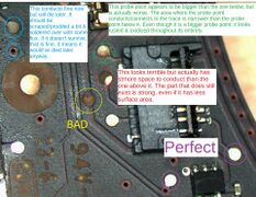
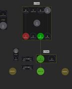
Probe point inspection (Figure 1)
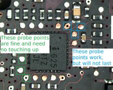
Probe point example (Figure 2)
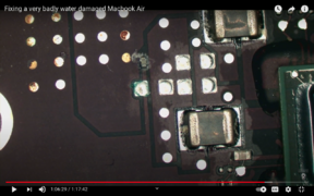
Example of corrosion on a MacBook (Figure 3)


Probe points allow signals and power rails to pass while providing an exposed point for measurements. These points can corrode and break, requiring attention to detail for effective repair.
Let's take the board on figure 1 as an example. Knowledge of the one wire circuit and its role in creating a green light on the charger, would be necessary if using your brain for this board repair. Knowledge of how a logic gate works and the ability to see the data on a logic analyzer would help to see what is going on in the SYS_ONEWIRE line. To fix this board on a brains level, requires quite a bit of knowledge and experience.
Here are examples of corroded probe points from a liquid-damaged MacBook Air: Video Link
An example from a video where a corroded probe point prevented a MacBook Air from turning on: Video Link
Short Circuit by Moisture

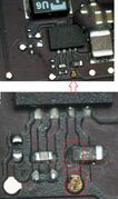
In figure 4, that may look like dust that does negligible damage, but it is partially short circuiting the pins. This can often be fixed with flux and solder.
Recognizing Corrosion Underneath a BGA Package
Sometimes, corrosion may be underneath chips. Most modern technology makes use of BGA chipsets - ball grid array, where all of the conducting points are underneath the chip. The chip is sitting on a bunch of balls that conduct electricity to pads on the logic board. Sometimes it will be obvious, but in cases like below, it will require a trained eye to recognize the corrosion. Can you see it in figure 5?

Working Components & Solder Joints That Won't Last
Working circuit that might not last (Figure 6)
Board view of figure 6's circuit (Figure 7)
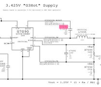
Schematic view of figure 6's circuit (Figure 8)
Another example of a board being ultrasonically cleaned before resolving corrosion. (Figure 9)
after ultrasonic cleaning (Figure 10)


Components with corrosion may appear functional for testing but won't last. Proper rework is essential to ensure long-lasting repairs. It is generally a good idea to leave ultrasonic cleaning for the end. Once the board is ultrasonically cleaned, and the evidence of the water damage are removed - the corroded areas become very difficult to spot.
Not all test points are crucial however, Look at figure 6. The bad probe point has a signal passing through it - in that case, from a connector, to the chip on the bottom right. Here, the probe point is for testing/measurement purposes only. That path goes to P3V42G3H_BOOST - which only goes to that one capacitor, and nothing else! The schematic and the board view (figure 7 & 8) confirms that pin 3 of U7090 goes to pin 1 of C7094, not any other component/chip. The trace is already intact from the chip to the capacitor. The probe point that is under the capacitor serves no functional purpose. However, the capacitor & its solder pad do, and must be reworked.
Bad Legs on Chips

Make sure to inspect the legs of various ICs, It might not always be very obvious.
Inspect at an Angle
Tilting the board reveals hidden corrosion that may not be visible straight on.

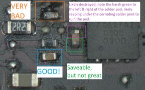
Examples of Poor Soldering
Ensure even joints that naturally flow into place. Proper soldering prevents clumps and incomplete joints.


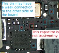
Can You See What's Wrong?
Here's an exercise for you. Can you spot the issue on figure 15?
