| AMD Polaris (RX 400/500) GPU Diagnosing Guide | |
|---|---|
| Type | Troubleshooting/Diagnostics |
| Device(s) | RX 460, RX 470, RX 480, RX 560, RX 570, RX 580, RX 590 |
| Difficulty | ◉◉◌◌ Medium |
This guide is applicable to most Polaris cards ranging from the 460 to the 590 series. While some vendors may produce different PCBs or utilize distinct components, the general operational principles for these cards are typically consistent unless otherwise specified. This guide uses a reference RX 480 as an example.
Have any questions or need assistance with a specific GPU problem? Feel free to post on /r/GPURepair!
The Card Layout
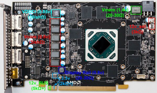
PCB Image courtesy of TechPowerUp
Before proceeding, it's advisable to inspect the card for physical damage, especially in the case of cards without a backplate. They can easily lose some components on the back due to poor handling.
Once you've confirmed there is no physical damage to the card, you can proceed with a multimeter to check the resistances of the voltage rails.
Step 1: Base Voltage Rails (12V, 3.3V)
Base voltages are supplied to the card through the motherboard and the external 8-pin power connector(s). Learn more about What are the Base Voltage rails for GPUs?
12V Rails
The card receives 12V power via the PCIe slot and additional 6-8 pin connector(s).
Begin by measuring the resistances of the 12V rail originating from the PCIe slot (first 3 pins, see Figure 1).
Subsequently, measure each inductor for external power connectors (some higher end cards have multiple external power connectors, and each of them has its own inductor, so measure each one individually).
The resistance value may vary from card to card, but it should generally be in the thousands+ Ω range. If you measure 50Ω or less, you likely have a short on the card.
Solution: Refer to this page dedicated to Base Voltage Rail Short on Polaris GPUs.
3.3V Rail
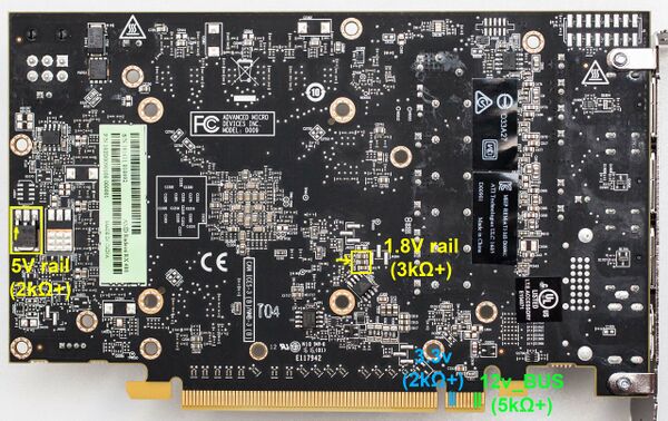
The card derives 3.3V power solely from the PCIe slot. It is obtained from the 4th pin going left from the PCIe key notch in the front and the 2nd and 3rd pins on the back going from the notch again (as depicted in Figures 1 and 2).
If you measure less than 50Ω on one or multiple base rails, you likely have a card with a short. In such cases, the computer may not turn on because the power supply activates overcurrent protection (OCP).
Solution: Check out this page dedicated to Base Voltage Rail Short on Polaris GPUs.
**On MSI RX cards, the 3.3V pin typically has a resistance to ground of about 200 ohms.
If there is no short, you can continue with the troubleshooting.
Step 2: Minor Voltage Rails (5V, 1.8V, Display Rail, VMem, VCore, and VDDCI)
Minor voltage rails are generated by the card itself using the base rails, either through Linear Voltage Regulators or Step Down Buck Converters.
Check the resistance of the output of these rails and compare them with Figures 1 and 2. VCore has such low resistance that measuring its resistance may not be very useful. A more helpful approach is to measure its resistance against the 12V rails, not GND.
If you measure lower resistance on one or more of these rails, refer to their respective pages for more information.
Otherwise, you can continue with the guide.
Step 3: Powering On the Card
Assuming there are no shorts, you can proceed to plug the card into the motherboard and start testing. Alternatively, you can use a Lab Bench Power Supply and a riser to test the card, which is safer for the motherboard and offers more flexibility in moving the card around and monitoring its current draw in case of a short.
Set your multimeter to DC Voltage mode and begin by measuring the base rails first. If they are present, proceed to measure the minor rails.
Minor rails activate in series, so if one doesn't start, the subsequent ones in the series won't activate either.
Power Sequence
In most Polaris GPUs, they typically activate in the following order:
5V → 1.8V → Display Rail → VMem/VDDCI → VCore (In some cases, VDDCI may activate after VMem, while in other cases, VDDCI and VCore are controlled by the same controller and activate simultaneously.)
For example, if the 5V rail doesn't activate, nothing else in the chain will activate either, which means no fan spin if there's an issue with 5V or 1.8V.
If you're missing one of them, refer to their respective pages for more details on how they work and potential issues:
Step 4: No Video Output
If everything is in order, but there is still no video output, some of these factors may be at play, including faulty memory, BIOS, PERSTB, Crystal oscillator, GPU chip, or strap issues. Also, if the HDMI port displays a black screen, try connecting the monitor to one of the display ports on the graphics card; you may obtain an image through the display port.
Memory Problems
If you've reached this point, the most likely culprit is the memory. You can confirm this by testing the memory in Linux. Refer to the AMD Memory Testing Guide for instructions on detecting faulty memory chips.
BIOS Problems
If the memory is fine or the card isn't even detected in Linux, the issue is likely related to the BIOS. Check out the BIOS Problems on Polaris GPUs page for guidance.
Crystal Oscillator
Crystal oscillators, often marked with "Y" followed by a number, can occasionally fail, resulting in the card not booting up. In most Polaris GPUs, the oscillator frequency is 27MHz. To test it, you'll need an oscilloscope or a multimeter with an Hz function that can exceed 27MHz.
PERSTB Signal
U100 is a multiple function gate, the output of which is determined by the 3 inputs shown in figure 3. Since input A is always high (direct connection to 3.3V rail) according to the datasheet, the output will go high only if the other 2 inputs (B & C) are also high.
Sometimes this gate can fail which results in the output Y "PERSTb_BUF" signal not getting generated and prevent the card from working.
Start by checking all inputs, if one is missing trace it according to the schematic in figure 3 and replace the faulty components. If all the inputs are present but the output is low, check the Vcc pin and make sure the gate is powered, after that, replace it if all inputs and power is present on the gate.
If everything else is working as they should but still no video out then unfortunately you have a faulty GPU core. Best use for that card is as spare parts since getting hold of a GPU chip by itself is very hard and expensive and replacing it is a very advanced procedure that requires a BGA rework station and it's out of reach for many people.
Step 5: GPU outputs a picture
perhaps the card does output a picture but it is not working properly, here are the common problems and their potential fixes.
Artifacting
Artifacting is most often caused by memory problems, check AMD Memory Testing Guide
if you do not get memory errors even after 100+MB test in MATS then the core is very likely to be the issue.
Error 43
just like artifacting, error 43 can be caused by faulty memory or core but also BIOS and straps.
Start by making sure the memory is fine as shown in the guide above, then check if the BIOS is not corrupted/modded (flash original bios from either TPU BIOS Library or manufacturer's site) and check the bios circuit as shown here: BIOS Problems on Polaris GPUs.
After that if the problem persists, check the strap resistors, they can either get knocked off or change in value which will trigger error 43.
If everything is fine but the error persists then the core itself is damaged.


