| Resistors - Repair Basics | |
|---|---|
| Type | |
| Device(s) | |
| Difficulty | |
This article aims to provide a comprehensive overview of resistors from a repair perspective, detailing their function, types, common issues, testing methods, and replacement considerations.
What is a resistor?
A resistor is a fundamental electrical component found in every single electronic device and circuit. Its role is controlling the flow of electric current within a circuit (limit the current).
Resistors are measured in "Ohms (Ω)"
Function
Even though resistors can only limit the current, they can be used in clever ways -using physical laws- to perform different functions in electrical circuits. Here are a few common ones:
Voltage divider
A voltage divider is an electrical circuit that divides a higher input voltage into a lower output voltage using two or more resistors in series. It is commonly used to create reference voltages or reduce voltage levels for specific applications in electronics.
The output voltage is determined by the ratio of the resistance values in the circuit like so:
Voltage Divider formula (assuming NO LOAD on Vout):
Uses:
- Reference Voltage: Voltage dividers are employed to create stable reference voltages for sensor calibration, analog signal processing, and feedback in control systems.
- Voltage Scaling: They can be used to scale down high input voltages to levels suitable for analog-to-digital converters (ADCs) or microcontrollers, ensuring safe and accurate measurements.
- Biasing Transistors: Voltage dividers set the base voltage of transistors in amplifier and switching circuits, influencing their behavior.
- Voltage Monitoring: In battery-powered devices, voltage dividers are used to monitor the battery voltage to determine its state of charge.
- Voltage Regulation: In some cases, voltage dividers are used in conjunction with other components to approximate voltage regulation in simple power supply circuits.
- And much more
Resistor sensors
Resistor sensors, also known as resistive sensors, are a class of sensors that rely on changes in resistance to detect and measure various physical phenomena, such as temperature or light
Pull-up / Pull-down
Pull-up and pull-down resistors are commonly used in digital electronics to ensure that a digital input signal is in a known state when it's not actively being driven by an external source. They are essential for preventing floating or undefined states A pull-up resistor connects a digital input to a voltage level (usually Vcc, which is the supply voltage). This effectively "pulls up" the input to a logical HIGH state when the switch or sensor is not actively grounding it. Pull-up resistors are often used with switches and sensors that are normally open. When the switch is closed or the sensor is active, it grounds the input, causing it to read as LOW. When the switch is open or the sensor is inactive, the pull-up resistor ensures the input reads as HIGH. A pull-down resistor connects a digital input to ground (GND). This "pulls down" the input to a logical LOW state when the switch or sensor is not actively driving it HIGH. Pull-down resistors are typically employed with switches and sensors that are normally closed. When the switch is open or the sensor is inactive, it keeps the input grounded (LOW). When the switch is closed or the sensor is active, it drives the input HIGH. Usually, pullup or pulldown resistors are 2.2k to 10k ohms.
Current measurement
Current measurement using shunt resistors is a widely used method in electronics and electrical engineering to accurately measure the current flowing through a circuit.
The principle behind this technique is Ohm's Law
A low resistance, precise "Shunt" resistor is used in series with the rest of the circuit "load" to measure the current flowing in said circuit by measuring the voltage drop across the shunt. In some cases, the voltage drop is very tiny and needs to be amplified using Op-Amps. In modern electronics, specialized Integrated Circuits "ICs" are used to measure the voltage drop/current draw.
The shunt resistor is specifically designed with a known and well-calibrated resistance value, very close to 0 Ohms, usually 0.002.
Usually, the shunt resistor is placed where a fuse might be, where all the current passes through it. Sometimes, the shunt resistor itself acts as a fuse if a short circuit happens since it will be the highest resistance point in the circuit.
Types
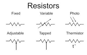
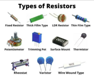
There are 4 main types of resistors:
Fixed value resistors
These are the most common type and come in various packages, sizes, and materials.
SMD Fixed value resistors
SMD (surface mount) resistors are usually black with numbers on top. They come in different sizes, and there are multiple standards for value marking, most common one is numeric where the last number is the multiplier or "number of zeroes" (for example, 221 on a resistor means 220 ohms).
"R" on SMD resistors means a dot "." (for example 5R60 means 5.60 Ohms)
Here is an online calculator for the 3 widely used standards.
THT Fixed value resistors
THT (Through Hole) resistors are varied in colors and sizes, they usually have colored bands on them to indicate their value. On ceramic type, the value is written.


